
A Micromechanical Gyroscope Based on Waveguide Grating Evanescent Field Disturbance Detection

A micro-machined gyroscope and waveguide grating technology, applied in the field of micro-inertial sensing, can solve the problems of low flexibility in structural design, difficult mechanical and optical properties, etc., and achieve the effect of supporting mechanical and optical properties and supporting independent optimization.

Inactive Publication Date: 2020-11-20
BEIHANG UNIV
View PDF10 Cites 0 Cited by
  • Summary
  • Abstract
  • Description
  • Claims
  • Application Information

AI Technical Summary

Problems solved by technology

However, in the current MEMS inertial devices based on grating displacement detection technology, the grating is not only the key structure of the mechanical sensitive unit, but also the key structure of the optical detection unit, so it is difficult to achieve independent optimization of mechanical properties and optical properties, and the flexibility of structural design is low.

Method used


Image

  • A Micromechanical Gyroscope Based on Waveguide Grating Evanescent Field Disturbance Detection
  • A Micromechanical Gyroscope Based on Waveguide Grating Evanescent Field Disturbance Detection
  • A Micromechanical Gyroscope Based on Waveguide Grating Evanescent Field Disturbance Detection

Examples


Embodiment Construction

[0038] The following will clearly and completely describe the technical solutions in the embodiments of the present invention with reference to the accompanying drawings in the embodiments of the present invention. Obviously, the described embodiments are only some, not all, embodiments of the present invention. Based on the embodiments of the present invention, all other embodiments obtained by persons of ordinary skill in the art without making creative efforts belong to the protection scope of the present invention.

[0039] The purpose of the present invention is to provide a micromechanical gyroscope based on waveguide grating evanescent field disturbance detection, which realizes the independence of mechanical structure and optical structure, thereby supporting independent optimization of mechanical performance and optical performance.

[0040] In order to make the above objects, features and advantages of the present invention more comprehensible, the present invention w...


PUM


Abstract

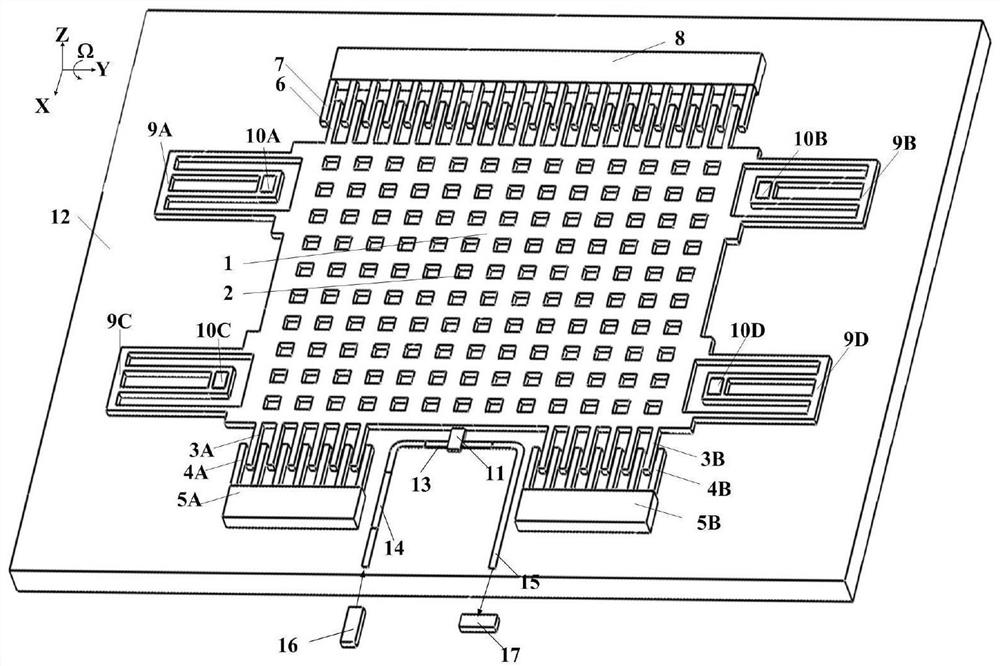
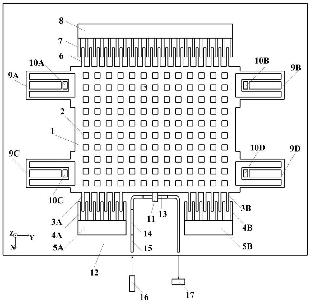
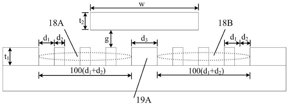
The invention discloses a waveguide grating evanescent field disturbance detection-based micromechanical gyroscope micromechanical gyroscope. According to the gyroscope, a driving electrode and a monitoring electrode are distributed on two sides of a mass block; one end of the driving electrode is fixedly connected with the mass block, and the other end of the driving electrode is fixed onto a silicon dioxide substrate; one end of the monitoring electrode is fixedly connected with the mass block, and the other end of the monitoring electrode is fixed onto the substrate; by means of an electricfield, the driving electrode drives the mass block to vibrate in a horizontal direction; the monitoring electrode detects the vibration amplitude of the mass block; a disturbance beam and the drivingelectrode are located on the same side of the mass block; the disturbance beam is fixedly connected with the center of the side edge of the mass block; the laser emergent direction of a laser is directly opposite to one end of an optical waveguide; the other end of the optical waveguide is directly opposite to a detector; a waveguide grating cavity is arranged on the optical waveguide; the waveguide grating cavity is located below the disturbance beam; and the disturbance beam is located in the evanescent field of the waveguide grating cavity. According to the micromechanical gyroscope of theinvention, a mechanical structure and an optical structure can be separate, so that the independent optimization of mechanical performance and optical performance can be supported.

Description

technical field [0001] The invention relates to the technical field of micro-inertial sensing in micro-mechanical systems, in particular to a micro-mechanical gyroscope based on waveguide grating evanescent field disturbance detection. Background technique [0002] Micromachined gyroscope (also known as MEMS gyroscope) is an inertial device that realizes angular velocity sensing by measuring Coriolis acceleration. It has small size, light weight, low cost, low power consumption, high integration, shock resistance, and With advantages such as mass production, it has become an important inertial sensor device in tactical-level and low-to-medium precision inertial navigation systems. [0003] Micromechanical gyroscopes ultimately need to measure the inertial displacement of the mass to achieve angular velocity sensing, so from the perspective of detection, the micromechanical gyroscope can be regarded as a micro-displacement sensor. Compared with the driving mode, the vibratio...

Claims


Application Information

Patent Timeline
Patent Type & Authority Patents(China)
IPC IPC(8): G01C19/5649G01C19/5656
CPCG01C19/5649G01C19/5656
Inventor 周震赵玉娇王奕奕
Owner BEIHANG UNIV
Learn More