Dispensing equipment for energy saving lamp manufacturing

A technology for energy-saving lamps and glue dispensing, which is applied to devices and coatings for coating liquid on the surface, and can solve the problems of easy coagulation of colloids and difficulty in controlling the amount of glue dispensed

Inactive Publication Date: 2017-07-04
GRACE(NINGBO) LIGHTING CO LTD
View PDF7 Cites 8 Cited by
  • Summary
  • Abstract
  • Description
  • Claims
  • Application Information

AI Technical Summary

Problems solved by technology

[0005] In order to overcome the shortcomings of the prior art that the colloid is easy to coagulate and the amount of glue dispensed is difficult to control, the technical problem to be solved by the present invention is to provide a dispensing device for making energy-saving lamps that is not easy to coagulate and can easily control the amount of glue dispensed

Method used


Image

  • Dispensing equipment for energy saving lamp manufacturing
  • Dispensing equipment for energy saving lamp manufacturing
  • Dispensing equipment for energy saving lamp manufacturing

Examples


Embodiment 1

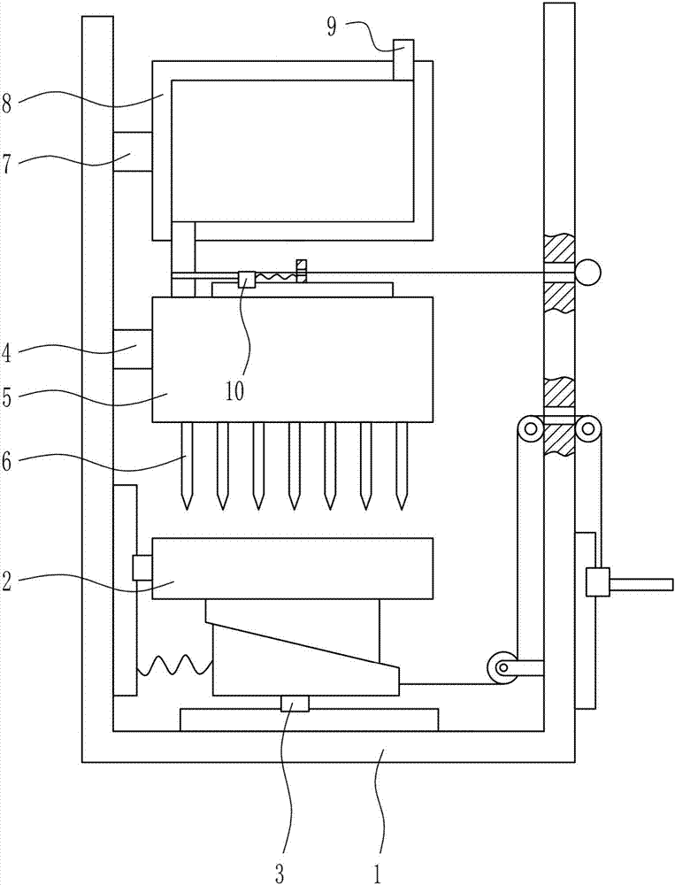
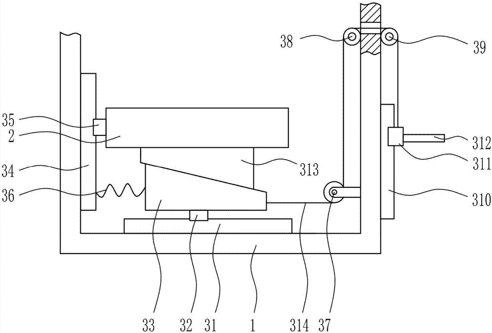
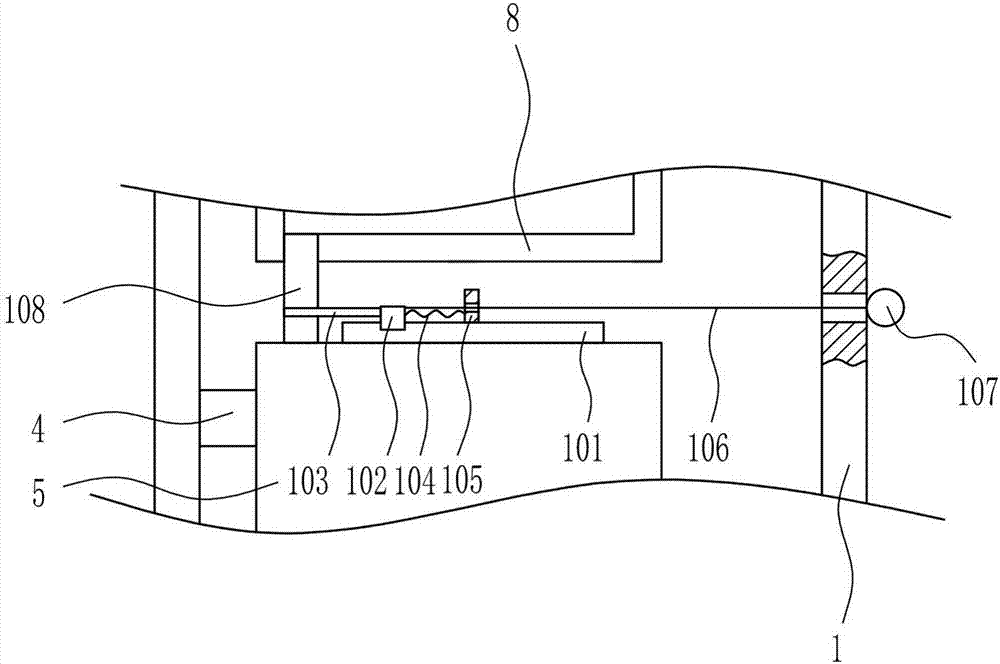
[0030] A kind of dispensing equipment for making energy-saving lamps, such as Figure 1-5 As shown, it includes a mounting frame 1, a placement plate 2, a lifting device 3, a first support rod 4, a storage tank 5, a dispensing head 6, a second support rod 7, a box body 8, a feeding pipe 9 and a blanking Device 10, the inner bottom of the installation frame 1 is provided with a lifting device 3, the top of the lifting device 3 is provided with a placement plate 2, the middle part of the left wall of the installation frame 1 is provided with a first pole 4, and the right end of the first pole 4 is connected to a storage tank 5. The bottom of the storage tank 5 is evenly equipped with a dispensing head 6, and the upper part of the left wall of the installation frame 1 is provided with a second pole 7. The right end of the second pole 7 is connected to the box body 8, and the top right side of the box body 8 is provided with a A feed pipe 9 , a feeding device 10 is connected betwe...

Embodiment 2

[0032] A kind of dispensing equipment for making energy-saving lamps, such as Figure 1-5 As shown, it includes a mounting frame 1, a placement plate 2, a lifting device 3, a first support rod 4, a storage tank 5, a dispensing head 6, a second support rod 7, a box body 8, a feeding pipe 9 and a blanking Device 10, the inner bottom of the installation frame 1 is provided with a lifting device 3, the top of the lifting device 3 is provided with a placement plate 2, the middle part of the left wall of the installation frame 1 is provided with a first pole 4, and the right end of the first pole 4 is connected to a storage tank 5. The bottom of the storage tank 5 is evenly equipped with a dispensing head 6, and the upper part of the left wall of the installation frame 1 is provided with a second pole 7. The right end of the second pole 7 is connected to the box body 8, and the top right side of the box body 8 is provided with a A feed pipe 9 , a feeding device 10 is connected betwe...

Embodiment 3

[0035] A kind of dispensing equipment for making energy-saving lamps, such as Figure 1-5 As shown, it includes a mounting frame 1, a placement plate 2, a lifting device 3, a first support rod 4, a storage tank 5, a dispensing head 6, a second support rod 7, a box body 8, a feeding pipe 9 and a blanking Device 10, the inner bottom of the installation frame 1 is provided with a lifting device 3, the top of the lifting device 3 is provided with a placement plate 2, the middle part of the left wall of the installation frame 1 is provided with a first pole 4, and the right end of the first pole 4 is connected to a storage tank 5. The bottom of the storage tank 5 is evenly equipped with a dispensing head 6, and the upper part of the left wall of the installation frame 1 is provided with a second pole 7. The right end of the second pole 7 is connected to the box body 8, and the top right side of the box body 8 is provided with a A feed pipe 9 , a feeding device 10 is connected betwe...


PUM


Abstract

The invention relates to dispensing equipment, and especially relates to dispensing equipment for energy saving lamp manufacturing. The invention aims to provide dispensing equipment having the advantages that the adhesive is difficult to cure and the adhesive amount can be controlled easily. The provided dispensing equipment comprises an installation rack, a disposing plate, an elevating device, a first support rod, a material storage tank, and dispensing heads. The elevating device is installed in the installation rack. The top of the elevating device is provided with the disposing plate. The middle of the left wall in the installation rack is provided with the first support rod. The right end of the first support rod is connected to the material storage tank. Dispensing heads are evenly arranged on the bottom of the material storage tank. A second support rod is arranged on the upper part of the left wall in the installation rack. The right end of the second support rod is connected to a box. The right side of the top of the box is provided with a feed pipe. By pressing a pedal, an LED support, which is placed on the disposing plate and needs to be dispensed, is raised to a proper height, the dispensing position becomes more accurate, and the dispensing effect is better.

Description

technical field [0001] The invention relates to a glue dispensing device, in particular to a glue dispensing device for making an energy-saving lamp. Background technique [0002] Energy-saving lamps, also known as energy-saving bulbs, electronic bulbs, compact fluorescent lamps and integrated fluorescent lamps, refer to lighting equipment that combines fluorescent lamps and ballasts into a whole. In 2008, the state launched the "Green Lighting" project, and urban and rural residents and enterprises enjoy a certain percentage of subsidies for using energy-saving lamps from winning bidders. The promotion of energy-saving lamps is of great significance, however, the harm of waste energy-saving lamps to the environment has also attracted attention. By the end of October 2012, hundreds of millions of energy-saving lamps were scrapped in the energy-saving promotion project, each of which can pollute 180 tons of water and five or six acres of soil. The problem of disposal and rec...

Claims


Application Information

Patent Timeline
Patent Type & Authority Applications(China)
IPC IPC(8): B05C5/02B05C13/02B05C11/10B05C11/11
CPCB05C5/027B05C11/1047B05C11/11B05C13/02
Inventor 张晓艳
Owner GRACE(NINGBO) LIGHTING CO LTD
Why Eureka
Try Eureka