Residual oscillation suppression method for flexible manipulator

A flexible robotic arm and residual vibration technology, applied in the field of robotics, can solve problems such as poor effects and achieve simple, easy-to-implement, and robust effects

Active Publication Date: 2017-07-04
SHENZHEN GRADUATE SCHOOL TSINGHUA UNIV
View PDF3 Cites 13 Cited by
  • Summary
  • Abstract
  • Description
  • Claims
  • Application Information

AI Technical Summary

Problems solved by technology

[0004] The above methods are all model-based control methods. These methods often require accurate physical models and w

Method used


Image

  • Residual oscillation suppression method for flexible manipulator
  • Residual oscillation suppression method for flexible manipulator
  • Residual oscillation suppression method for flexible manipulator

Examples


Embodiment Construction

[0059] The present invention will be further described below with reference to the accompanying drawings and in combination with preferred embodiments.

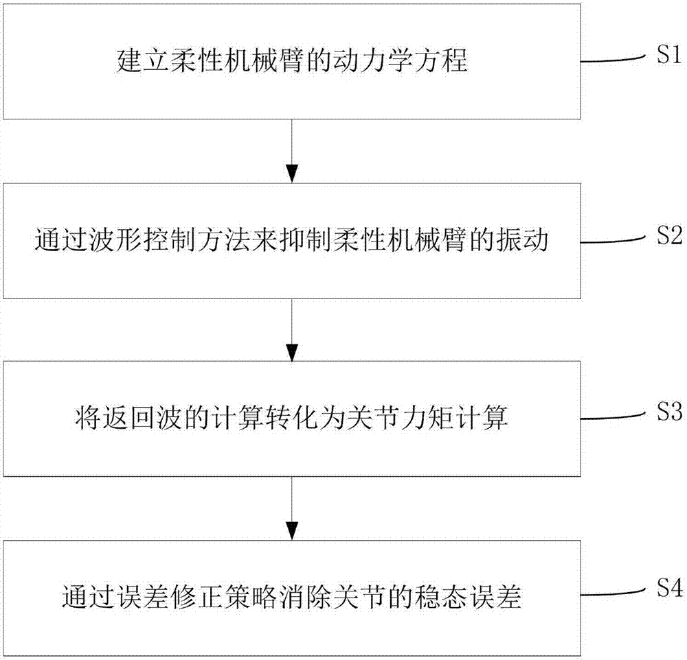
[0060] Such as figure 1 As shown, the residual vibration suppression method of the flexible manipulator of the preferred embodiment of the present invention includes the following steps:

[0061]S1: Establish the dynamic equation of the flexible manipulator, including:

[0062] S11: Establish the dynamic equation of rigid joint-flexible manipulator:

[0063] From the kinetic energy and potential energy of the system, using the Lagrangian equation, after derivation, the dynamic equation of the rigid joint-flexible manipulator is obtained as:

[0064]

[0065] Among them, M 11 , M 22 is the inertia matrix of boom 1 and 2, M 12 is the coupling inertia matrix between the two arms, k is the equivalent stiffness of the arms, is the coupling matrix including Coriolis force and centrifugal force, q is the rotation angle of ...


PUM


Abstract

The invention discloses a residual oscillation suppression method for a flexible manipulator. The residual oscillation suppression method comprises the following steps: S1, building a kinetic equation of the flexible manipulator; and S2, suppressing oscillation of the flexible manipulator through a waveform control method. The residual oscillation suppression method for the flexible manipulator can realize oscillation suppression of the flexible manipulator without an accurate physical model.

Description

technical field [0001] The invention relates to the technical field of robots, in particular to a method for suppressing residual vibration of a flexible mechanical arm. Background technique [0002] The space manipulator is the core equipment for on-orbit assembly and maintenance of spacecraft. With the development of on-orbit service technology, it becomes more and more important as an effective means of task execution. However, due to the large operating space and light weight of the space manipulator, The problem of flexibility is more prominent. Among them, the flexibility mainly comes from two aspects: joint flexibility and arm flexibility. On the one hand, the flexibility of the manipulator will cause the vibration of the system to reduce the operation accuracy of the end of the manipulator. On the other hand, it will greatly increase the control difficulty of the system. The modeling and vibration control research of the arm is very important. [0003] At present, ...

Claims


Application Information

Patent Timeline
IPC IPC(8): B25J9/16B25J17/00B25J19/00
CPCB25J9/1633B25J17/00B25J19/0091
Inventor 刘厚德李亚南梁斌王学谦
Owner SHENZHEN GRADUATE SCHOOL TSINGHUA UNIV
Why Eureka
Try Eureka