Locked detection circuit applied to phase locked loop (PLL) with dynamic reconfigurable frequency dividing ratio

A technology of lock detection and frequency division ratio, applied in the direction of electrical components, automatic power control, etc., can solve the problems of unable to detect the locked state of the phase-locked loop in time, the feedback clock signal is unstable, the output clock signal is unstable, etc., to achieve The effect of increasing complexity, simple structure and excellent performance

Inactive Publication Date: 2011-02-16
CHANGSHA JINGJIA MICROELECTRONICS
View PDF7 Cites 13 Cited by
  • Summary
  • Abstract
  • Description
  • Claims
  • Application Information

AI Technical Summary

Problems solved by technology

Although the structure of this lock detection circuit realizes the judgment of the phase-locked loop frequency lock and the implementation process is relatively simple, it may not be able to correctly reflect the locked state of the phase-locked loop, because the feedback clock signal will be unstable before locking ( fast and slow), if the preset fixed time is short, the count value of the reference clock signal and the count value of the feedback clock signal may be the same within the fixed time, but in fact the output clock signal of the phase-locked loop is still Unstable, this will cause misjudgment of the lock state
In order to ensure that the locked state of the phase-locked loop is detected correctly, the fixed time is usually set long enough, so that even if the output clock signal is stable, the next stage circuit needs to wait until the fixed time, so it cannot be detected in time To the locked state of the phase-locked loop, and because the detection is performed within a fixed time, the short-term loss of lock that may occur during the frequency locking process cannot be handled

Method used


Image

  • Locked detection circuit applied to phase locked loop (PLL) with dynamic reconfigurable frequency dividing ratio
  • Locked detection circuit applied to phase locked loop (PLL) with dynamic reconfigurable frequency dividing ratio
  • Locked detection circuit applied to phase locked loop (PLL) with dynamic reconfigurable frequency dividing ratio

Examples


Embodiment Construction

[0012] The present invention will be described in further detail below in conjunction with the accompanying drawings and specific embodiments.

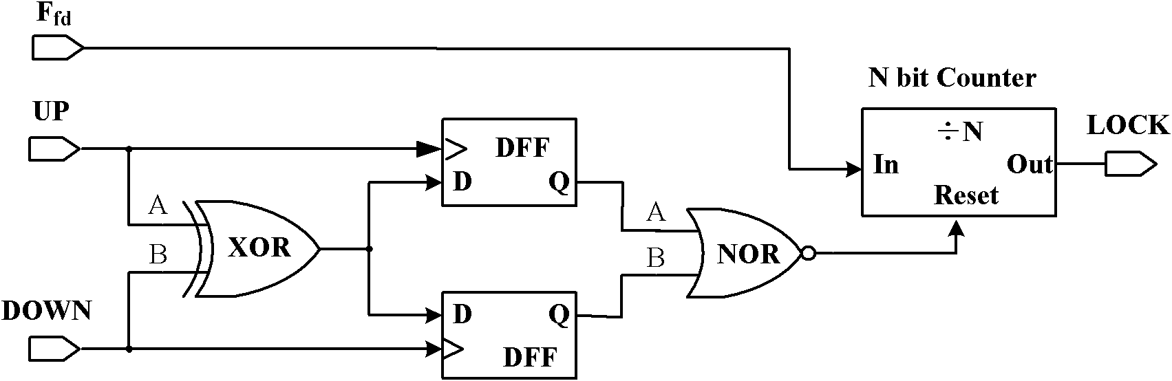
[0013] Such as figure 2 As shown, the lock detection circuit of the present invention applied to a PLL with a dynamically reconfigurable frequency division ratio includes an exclusive OR gate unit (X1), two D flip-flop units (D1, D2), a NOR gate unit ( N1) and an N-bit counter unit (C1), the lock detection circuit applied to the PLL with a dynamically reconfigurable frequency division ratio uses the exclusive OR gate unit X1 as the input stage, and the two input terminals of the exclusive OR gate unit X1 (A, B) are the UP and DOWN signals output by the phase frequency detector (PFD), the output is connected to the D terminals of the two D flip-flop units (D1, D2), and the D1 and D2 units use the UP and DOWN signals as D The clock of the flip-flop samples the data output by the XOR gate unit X1. The output of the D1 and D2 units is c...


PUM


Abstract

The invention discloses a locked detection circuit applied to a phase locked loop (PLL) with dynamic reconfigurable frequency dividing ratio. The locked detection circuit comprises an exclusive or gate X1, two D triggers D1 and D2, an or not gate N1 and an N-bit counter C1. The locked detection circuit samples data output by the X1 through the D1 and D2; the A and B ends of the X1 are connected to UP and DOWN signals output by a phase frequency detector; the N1 is used for judging whether the pulse widths of the UP and DOWN signals are equal or not, if the pulse widths of the UP and DOWN signals are equal, the output of the N1 is high, the C1 starts to work, after the output of the N1 is kept at high level for N periods, the C1 outputs an effective LOCK signal and the PLL is locked; and if the pulse widths of the UP and DOWN signals are not equal, the output of the N1 is low, the C1 is kept at a reset state, the LOCK is low and the PLL is not locked. The locked detection circuit has a simple structure and can quickly and accurately detect the lock state of the PLL under any input reference frequency and output frequency.

Description

technical field [0001] The invention mainly relates to the design field of a PLL and its locking detection circuit, in particular to a locking detection circuit applied to a PLL with a dynamically reconfigurable frequency division ratio. Background technique [0002] Phase-locked loop (PLL, Phase Locked Loop), as a very important module in analog circuits and digital-analog hybrid circuits, is widely used in system-on-chip (SOC, System on Chip) to provide accurate and stable clock signals. [0003] figure 1 Shown is the most basic phase-locked loop structure, which mainly includes the following components: phase frequency detector (Phase Frequency Detector, PFD), charge pump (Charge Pump, CP), loop filter (Low Pass Filter, LPF), Voltage Control Oscillator (Vo1tage Control Oscillator, VCO), in order to realize the function of dynamically reconfigurable frequency division ratio, it is also necessary to introduce a programmable between the input reference frequency and VCO out...

Claims


Application Information

Patent Timeline
IPC IPC(8): H03L7/08H03L7/113
Inventor 石大勇陈怒兴陈宝民蒋仁杰李俊丰郭斌谭晓强
Owner CHANGSHA JINGJIA MICROELECTRONICS
Why Eureka
Try Eureka