
Rail gnawing preventing device for hanging beam crown block, hanging beam crown block and traveling method thereof

A technology of crane beam cranes and rail-gnawing crane cranes, which is applied in safety devices, traveling mechanisms, transportation and packaging, and can solve problems such as difficult maintenance, good safety guarantees, and poor stability, and achieve installation and operation Convenience, good security, strong self-adaptive effects

Active Publication Date: 2017-07-04
CHINA RAILWAY ENG MASCH RES & DESIGN INST CO LTD
View PDF6 Cites 2 Cited by
  • Summary
  • Abstract
  • Description
  • Claims
  • Application Information

AI Technical Summary

Problems solved by technology

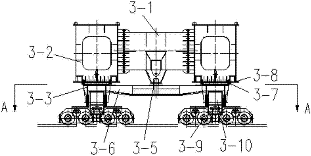
[0008] Another purpose of the present invention is to solve the disadvantages of poor reliability, difficult maintenance, high cost and poor stability of the anti-gnawing rail means in the prior art, and proposes an anti-gnawing rail device for crane beam cranes, Crane crane and its running method, the crane and its running method, the left and right longitudinal movement trolley and the longitudinal movement frame adopt the flexible connection form, the installation and operation are convenient, the structure is simple and compact, and the lower cover plate in the middle of the end beam of the frame adopts the waist eye hole Cooperating with the central hinge shaft with the round hole can release the lateral displacement caused by the deformation of the main beam of the frame, which has good safety guarantee

Method used


Image

  • Rail gnawing preventing device for hanging beam crown block, hanging beam crown block and traveling method thereof
  • Rail gnawing preventing device for hanging beam crown block, hanging beam crown block and traveling method thereof
  • Rail gnawing preventing device for hanging beam crown block, hanging beam crown block and traveling method thereof

Examples


Embodiment

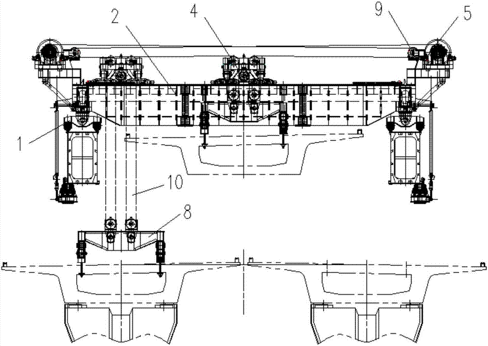
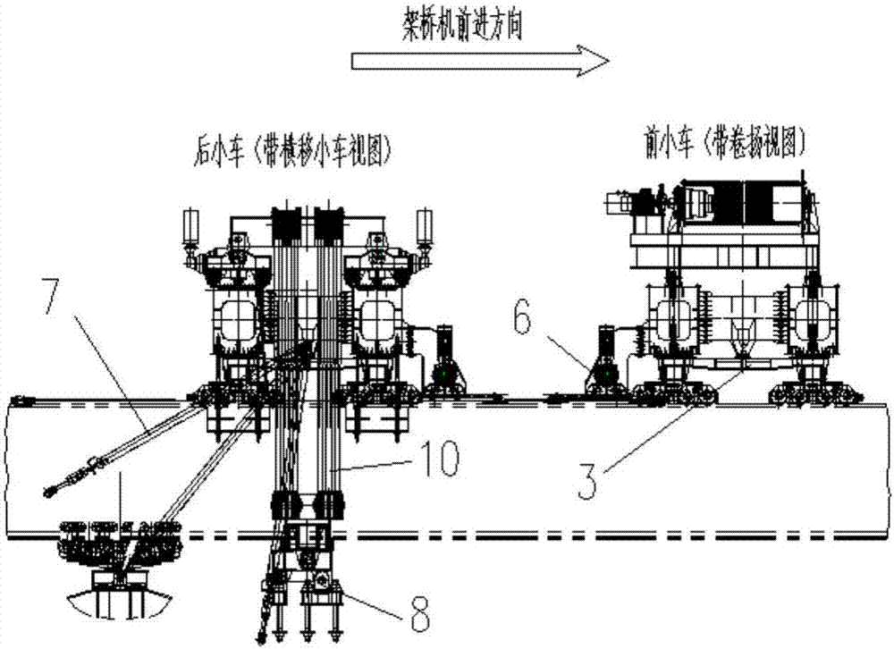
[0038] like Figure 1 to Figure 2 As shown, a single girder crane consists of two frame girders spanning the left and right bridge erecting machine arms and the left and right frame end beams to form a longitudinal moving frame 2 . The longitudinal movement driving mechanism 6 is flange-connected with the ends of the two main beams on the longitudinal movement frame 2. Steel rails are installed on the upper part of the main beam of the longitudinal movement frame 2 to provide support for the traverse trolley 4, and the lower part of the end beam is supported on the longitudinal movement. The trolley 1 can run longitudinally, and the hoist assembly 5 and the guide pulley block 9 on the traversing trolley 4 are provided on the outside of the end beam to provide vertical movement. The outer side of the beam works together with the longitudinal movement drive mechanism 6 to drive the arm of the bridge erecting machine to move longitudinally through the hole.

[0039] like Figur...


PUM


Abstract

The invention relates to rail gnawing preventing devices, crown blocks and traveling methods, belongs to the technical field of bridge girder erection machines, and particularly relates to a rail gnawing preventing device for a hanging beam crown block, the hanging beam crown block and a traveling method thereof. The rail gnawing preventing device comprises a connecting cross beam and a central hinge shaft, wherein the two ends of the connecting cross beam are connected with hinge supports of a trolley, one end of the central hinge shaft is fixedly connected with the middle of the cross beam, and the other end of the central hinge shaft extends into a connecting hole in the middle of a vehicle frame end beam. In order to guarantee that the longitudinal moving trolley is stressed in a balanced mode and adapts to sidewise bending deformation of a bridge girder erection machine arm, the middle of the crown block vehicle frame end beam is connected with the longitudinal moving trolley through the central hinge shaft, and the end of a vehicle frame main beam is directly supported on the longitudinal moving trolley. The rail gnawing preventing device can be automatically adjusted to adapt to rail gnawing, automatically release the sidewise action force between wheels and rails, and avoid long-time rail gnawing.

Description

technical field [0001] The invention relates to an anti-gnawing device, a crane and a running method, belonging to the technical field of bridge erecting machines, and in particular to an anti-gnawing device for a crane, a crane and a running method thereof. Background technique [0002] At present, large-tonnage bridge erecting machines are more and more widely used, and have the characteristics of large span, heavy lifting capacity, high lifting height, and high work level, which makes the design of the matching crane beam crane particularly important. In particular, due to manufacturing and installation errors, rail gnawing is prone to occur when the crane is running. Regular and long-term gnawing on rails will not only cause great damage to the rails, wheels, motors and other related equipment, but also affect the safe and stable operation of the equipment, seriously It may even lead to major safety accidents. [0003] At present, in addition to strictly controlling the...

Claims


Application Information

Patent Timeline
Patent Type & Authority Applications(China)
IPC IPC(8): B66C9/10B66C9/14B66C15/00
CPCB66C9/10B66C9/14B66C15/00
Inventor 舒俊仉传兴祖松鹤唐娅玲陈灵孟凡田周发扬
Owner CHINA RAILWAY ENG MASCH RES & DESIGN INST CO LTD
Learn More