Locomotive traction system fault diagnosis device and method

A technology of fault diagnosis device and traction system, which is applied in general control system, control/regulation system, test/monitoring control system, etc., can solve the problems of inaccurate results, large labor and material resources, and low degree of intelligence.

Inactive Publication Date: 2019-10-29
ZHUZHOU CSR TIMES ELECTRIC CO LTD
View PDF14 Cites 5 Cited by
  • Summary
  • Abstract
  • Description
  • Claims
  • Application Information

AI Technical Summary

Problems solved by technology

[0008] In view of this, the object of the present invention is to provide a fault diagnosis device and method for a locomotive traction system to solve the problem that the existing fault diagnosis device and

Method used


Image

  • Locomotive traction system fault diagnosis device and method
  • Locomotive traction system fault diagnosis device and method
  • Locomotive traction system fault diagnosis device and method

Examples


Embodiment 1

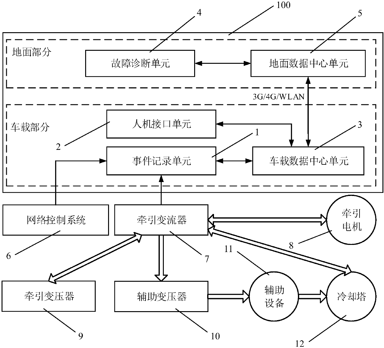
[0084] as attached figure 1Shown, a kind of embodiment of locomotive traction system fault diagnosis device, locomotive traction system fault diagnosis device 100 specifically comprises:

[0085] Vehicle parts and ground parts;

[0086] The vehicle part further includes an event recording unit 1 and a vehicle data center unit 3, and the ground part further includes a fault diagnosis unit 4 and a ground data center unit 5;

[0087] During the operation of the locomotive, the event recording unit 1 collects the data of the network control system 6 and the traction converter 7 in real time, and stores them as event recording files. When data analysis is required, the event record file is transmitted to the ground data center unit 5 via the vehicle-ground wireless transmission channel (3G / 4G / WLAN, etc.) through the vehicle-mounted data center unit 3 for data analysis. The analyzed data is input to the fault diagnosis unit 4, and the established neural network is used for fault d...

Embodiment 2

[0094] as attached Figure 4 Shown, a kind of embodiment of locomotive traction system fault diagnosis method specifically comprises the following steps:

[0095] S10) During the operation of the locomotive, the event recording unit 1 collects the data of the network control system 6 and the traction converter 7 in real time, and stores it as an event recording file;

[0096] S20) When data analysis is required, the event record file is transmitted to the ground data center unit 5 through the vehicle data center unit 3 via wireless transmission, and data analysis is performed;

[0097] S30) The analyzed data is input to the fault diagnosis unit 4, and the established neural network is used for fault diagnosis. The steady-state output of the fault diagnosis unit 4 is the specific cause of the fault of the traction system of the locomotive.

[0098] After step S30), the following steps are also included:

[0099] S40) The specific cause diagnosed by the fault diagnosis unit 4 ...


PUM


Abstract

The invention discloses a locomotive traction system fault diagnosis device and method. The device comprises a vehicle-mounted part and a ground part; the vehicle-mounted part further comprises an event recording unit and a vehicle-mounted data center unit, and the ground part further comprises a fault diagnosis unit and a ground data center unit. In a locomotive running process, the event recording unit collects data of a network control system and a traction converter in real time and stores the data as an event recording file. When data analysis is needed, the event recording file is transmitted to the ground data center unit through the vehicle-mounted data center unit in a wireless transmission mode, and data analysis is carried out. And the analyzed data is input to the fault diagnosis unit, fault diagnosis is carried out by using an established neural network, and the fault diagnosis unit steadily outputs specific reasons of the locomotive traction system fault. The technical problems that an existing locomotive traction system fault diagnosis device and method need to consume a large amount of manpower and material resources, and meanwhile the result is inaccurate can be solved.

Description

technical field [0001] The invention relates to the technical field of fault diagnosis, in particular to a fault diagnosis device and method applied to a traction system of a locomotive. Background technique [0002] During the operation of the locomotive, once the traction system fails, since there are many types of failures in the traction system itself, the causes of various types of failures are also different, and it is often difficult for drivers and passengers to troubleshoot the failures. At this time, if the traction system fails to return to normal after being reset many times, the locomotive will block the shaft where the traction system fails, and will also lose the corresponding shaft power, thereby seriously affecting the normal transportation of the whole train. Therefore, various scientific research institutes and related companies have also extensively carried out research on fault diagnosis of traction systems to assist drivers, maintenance personnel, and m...

Claims


Application Information

Patent Timeline
IPC IPC(8): G05B23/02
CPCG05B23/0243G05B2219/24065
Inventor 邓亚波杨卫峰刘勇文峥王成福王超李飞
Owner ZHUZHOU CSR TIMES ELECTRIC CO LTD
Why Eureka
Try Eureka