Wavelet de-noising method of optical-phase vibration

A wavelet denoising and optical phase technology, applied in the field of signal processing, can solve the problems of useful signal distortion, inability to achieve denoising, etc., and achieve strong adaptive effect.

Inactive Publication Date: 2013-05-01
新疆美特智能安全工程股份有限公司
View PDF2 Cites 6 Cited by
  • Summary
  • Abstract
  • Description
  • Claims
  • Application Information

AI Technical Summary

Problems solved by technology

Filter denoising is the most widely used method in practice, but it often results in distortion of useful signals while filtering out noise. It analyzes which frequency ranges of noise should be eliminated from the perspective of pure frequency domain
Moreover, if the overlapping area between the signal and noise frequency bands is large, the effect of denoising cannot be achieved.

Method used


Image

  • Wavelet de-noising method of optical-phase vibration
  • Wavelet de-noising method of optical-phase vibration
  • Wavelet de-noising method of optical-phase vibration

Examples


Embodiment Construction

[0032] The preferred embodiments of the present invention will be described below in conjunction with the accompanying drawings. It should be understood that the preferred embodiments described here are only used to illustrate and explain the present invention, and are not intended to limit the present invention.

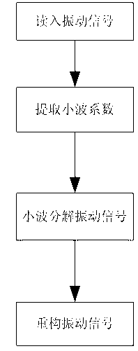
[0033] Such as figure 1 As shown, a wavelet denoising method of optical phase vibration, including the following steps:

[0034] a. Perform wavelet decomposition on the data: the specific formula is as follows:

[0035]

[0036] in Represents a noisy signal, which can be expressed as a data vector , ,... , is the real signal vector , ,... , is a Gaussian random vector , ,... , where the wavelet decomposition transform is a linear transform, represent the wavelet coefficients, is the noise level;

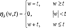
[0037] b. In the wavelet frequency domain, the wavelet coefficient generated by the effective signal has a large modulus; while the noise h...


PUM


Abstract

The invention discloses a wavelet de-noising method of optical-phase vibration. In a localized time-frequency analyzing method of which the size of a window (i.e. the area of the window) is fixed, but the shape of the window can be changed, and a time window and a frequency window can both be changed, a low-frequency part is provided with a wider time window and higher frequency resolution, and a high-frequency part is provided with a wider frequency window and higher time resolution, so that wavelet transformation has self-adaptability for signals so as to achieve the purposes of accurate de-noising and strong self-adaptability. Therefore, optical fibers can be accurately transmitted in a complicated electromagnetic environment.

Description

technical field [0001] The invention relates to the field of signal processing, in particular to a wavelet denoising method of optical phase vibration. Background technique [0002] With the development of optical fiber communication technology and optical signal processing technology, optical fiber sensing technology has rapidly developed into a hot technology in the field of engineering applications. Because its light waves are not afraid of electromagnetic interference, they are easy to be received by various photodetection devices, and can be easily used for photoelectric or electro-optical conversion. Easy to match with highly developed modern electronic devices and computers. Widely used in building deformation, temperature monitoring, airport perimeter, oil and gas pipeline leakage monitoring and other fields. According to the change of the physical characteristic parameters of the light wave modulated by the external signal, the modulation of the light wave can be d...

Claims


Application Information

Patent Timeline
Patent Type & Authority Applications(China)
IPC IPC(8): G01D3/032G01H9/00
Inventor 罗广迪司崇杰王文伟蒋海军
Owner 新疆美特智能安全工程股份有限公司
Why Eureka
Try Eureka