Convenient-to-assemble hydraulic valve

A hydraulic valve and convenient technology, applied in the field of hydraulic valve, can solve problems such as troublesome assembly, and achieve the effect of convenient initial positioning

Inactive Publication Date: 2017-07-04
NINGBO HAIHONG HYDRAULICS
View PDF0 Cites 0 Cited by
  • Summary
  • Abstract
  • Description
  • Claims
  • Application Information

AI Technical Summary

Problems solved by technology

In order to directly solve the problem of troublesome assembly in traditional technology

Method used


Image

  • Convenient-to-assemble hydraulic valve

Examples


Embodiment Construction

[0011] The specific implementation manners of the present invention will be further described in detail below in conjunction with the accompanying drawings and embodiments. The following examples are used to illustrate the present invention, but are not intended to limit the scope of the present invention.

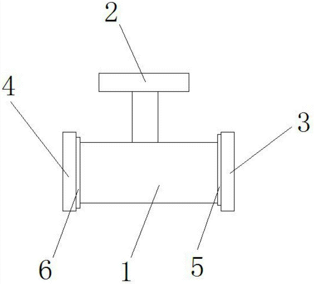
[0012] The structure of a hydraulic valve with easy assembly of the present invention is as follows: figure 1 As shown, it includes a valve housing 1 and an adjusting handle 2. The two ends of the valve housing 1 are respectively provided with a water inlet 3 and a water outlet 4. The rear end of the water inlet 3 is provided with a first magnet ring 5. The outlet The rear end of the nozzle 4 is provided with a second magnet ring 6, and the adjusting handle 2 is installed on the upper end of the valve casing 1 through a connecting rod.

[0013] Wherein, the material of the valve housing 1 is iron.

[0014] The beneficial effect of the invention is that the nozzles at bot...


PUM


Abstract

The invention discloses a convenient-to-assemble hydraulic valve which comprises a valve casing and an adjusting handle; a water inlet and a water outlet are formed in the two ends of the valve casing correspondingly; a first magnet ring is arranged at the rear end of the water inlet; a second magnet ring is arranged at the rear end of the water outlet; and the adjusting handle is arranged at the upper end of the valve casing. When the convenient-to-assemble hydraulic valve is mounted, pipe openings at the two ends can attract pipe openings to be connected, and preliminary location of a throttling valve is facilitated.

Description

technical field [0001] The invention relates to the field of hydraulic valves, in particular to a hydraulic valve with convenient assembly. Background technique [0002] The problem to be solved by the present invention is to provide a hydraulic valve that is easy to assemble. To directly solve the problem of troublesome assembly in the traditional technology. Contents of the invention [0003] (1) Technical problems to be solved [0004] Aiming at the deficiencies in the prior art, the present invention provides a hydraulic valve with simple structure and easy installation, which is easy to assemble. [0005] (2) Technical solution [0006] In order to achieve the above purpose, the present invention provides a hydraulic valve that is easy to assemble, including a valve casing and an adjusting handle, the two ends of the valve casing are respectively provided with a water inlet and a water outlet, and the rear end of the water inlet is provided with a second A magnet ...

Claims


Application Information

Patent Timeline
Patent Type & Authority Applications(China)
IPC IPC(8): F15B13/02
CPCF15B13/02
Inventor 邓波
Owner NINGBO HAIHONG HYDRAULICS
Why Eureka
Try Eureka