
Electromagnetic valve

A solenoid valve and spool technology, applied in the field of solenoid valves, can solve the problems of casing end wall rupture, low service life and rupture of solenoid valves, and achieve the effects of prolonging service life, ensuring reliability and reducing product costs

Active Publication Date: 2017-07-04
ZHEJIANG DUNAN MASCH CO LTD
View PDF8 Cites 2 Cited by
  • Summary
  • Abstract
  • Description
  • Claims
  • Application Information

AI Technical Summary

Problems solved by technology

In the 200,000-time action life test of the solenoid valve, the moving iron core drives the static iron core to hit the end wall of the conduit, which will cause the end wall of the casing to break, especially the fillet transition between the conduit side wall and the conduit end wall prone to rupture
Therefore, the existing solenoid valve has a low service life

Method used


Image

  • Electromagnetic valve
  • Electromagnetic valve
  • Electromagnetic valve

Examples


Embodiment Construction

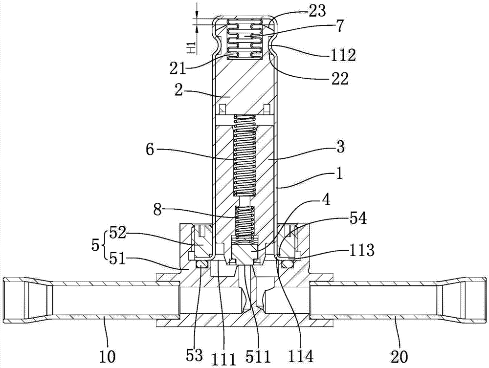
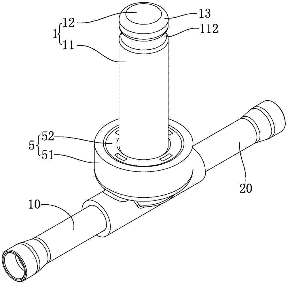
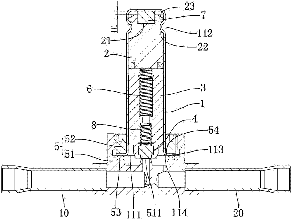
[0021] refer to figure 1 with figure 2 , the solenoid valve includes a conduit 1, a static iron core 2, a moving iron core 3, a valve core 4, a valve seat 5, a first elastic element 6, an A adapter 10 and a B adapter 20. In this embodiment, the first elastic element 6 is a helical spring. The catheter 1 includes a side wall 11 and an end wall 12 integrally formed with the side wall 11. The transition between the side wall 11 of the catheter 1 and the end wall 12 of the catheter 1 is through a rounded corner 13. A coil assembly is wound around the outer side of the side wall 11. The conduit 1 is provided with an assembly port 111, and the static iron core 2, the first elastic element 6, the moving iron core 3 and the valve core 4 are sequentially loaded into the conduit 1 through the assembly port 111; the valve seat 5 is provided with a valve port 511, a medium Inlet and medium outlet, when the static iron core 2, the first elastic element 6, the moving iron core 3 and the ...


PUM


Abstract

The invention relates to an electromagnetic valve. The problem that an electromagnetic valve is short in service life is solved. The electromagnetic valve comprises a conduit pipe, a static iron core, a movable iron core, a valve element and a valve base connected with the conduit pipe. The static iron core, the movable iron core and the valve element are all installed in the conduit pipe. The valve base is provided with a valve port. The movable iron core drives the valve element to open or close the valve port. The electromagnetic valve further comprises a buffer structure used for buffering force applied by the static iron core to the end wall direction of the conduit pipe, and the buffer structure is arranged between the static iron core and the end wall of the conduit pipe.

Description

technical field [0001] The invention relates to a solenoid valve. Background technique [0002] The solenoid valve includes a conduit, a static iron core and a moving iron core. The conduit is provided with an assembly port, and the static iron core and the moving iron core are respectively assembled into the conduit. The static iron core and the conduit are connected as one by riveting. When the solenoid valve is working, the moving iron core continuously hits the static iron core, and pushes the static iron core to move towards the end wall of the conduit. In the 200,000-time action life test of the solenoid valve, the moving iron core drives the static iron core to hit the end wall of the conduit, which will cause the end wall of the casing to break, especially the fillet transition between the conduit side wall and the conduit end wall prone to breakage. Therefore, the existing solenoid valve has a low service life. Contents of the invention [0003] The problem to ...

Claims


Application Information

Patent Timeline
Patent Type & Authority Applications(China)
IPC IPC(8): F16K31/06
CPCF16K31/0675
Inventor 汪昌东汪维奇
Owner ZHEJIANG DUNAN MASCH CO LTD
Learn More