Method and device for checking cabinet correction effect

A technology for correcting effects and cabinets, which is applied to the device for viewing the correction effects of cabinets, and in the field of viewing the correction effects of cabinets, which can solve the problems that random cabinet splicing is not easy to achieve, and the operation is not convenient.

Active Publication Date: 2019-10-29
XIAN NOVASTAR TECH
View PDF5 Cites 0 Cited by
  • Summary
  • Abstract
  • Description
  • Claims
  • Application Information

AI Technical Summary

Problems solved by technology

[0005] The embodiment of the present invention provides a method for checking the correction effect of the cabinet and a device for checking the correction effect of the cabinet, so as to solve the problem that it is not convenient to view the splicing effect of the cabinets when there are a large number of cabinets, and it is not easy to realize the splicing of random cabinets question

Method used


Image

  • Method and device for checking cabinet correction effect
  • Method and device for checking cabinet correction effect
  • Method and device for checking cabinet correction effect

Examples


no. 1 example

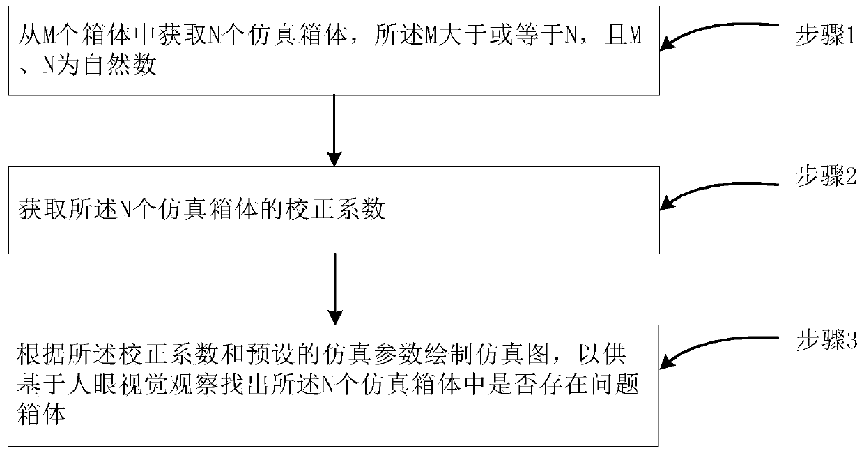
[0031] Such as figure 1 as shown, figure 1 It is a flow chart of a method for checking the effect of cabinet correction provided by the first embodiment of the present invention. The method includes the following steps:

[0032]Step 1. Obtain N simulated cabinets from M cabinets, where M is greater than or equal to N, and M and N are natural numbers;

[0033] Step 2, obtaining the correction coefficients of the N simulated cabinets;

[0034] Step 3. Draw a simulation diagram according to the correction coefficient and preset simulation parameters, so as to find out whether there is a problematic cabinet among the N simulated cabinets based on human visual observation.

[0035] Wherein, for step 1, it may be to select all, random multiple, front multiple, rear multiple or intermediate multiple cabinets as the N simulated cabinets from the M corrected cabinets.

[0036] Among them, for step 2, for the RGB full-color LED cabinet, each pixel includes red (R), green (G) and blue...

no. 2 example

[0047] This embodiment describes in detail the technical solutions of the embodiments of the present invention on the basis of the foregoing embodiments. Specifically, the method includes:

[0048] (1) Load the cabinet database, which can be a single database containing all cabinet correction coefficients, or multiple databases or a folder;

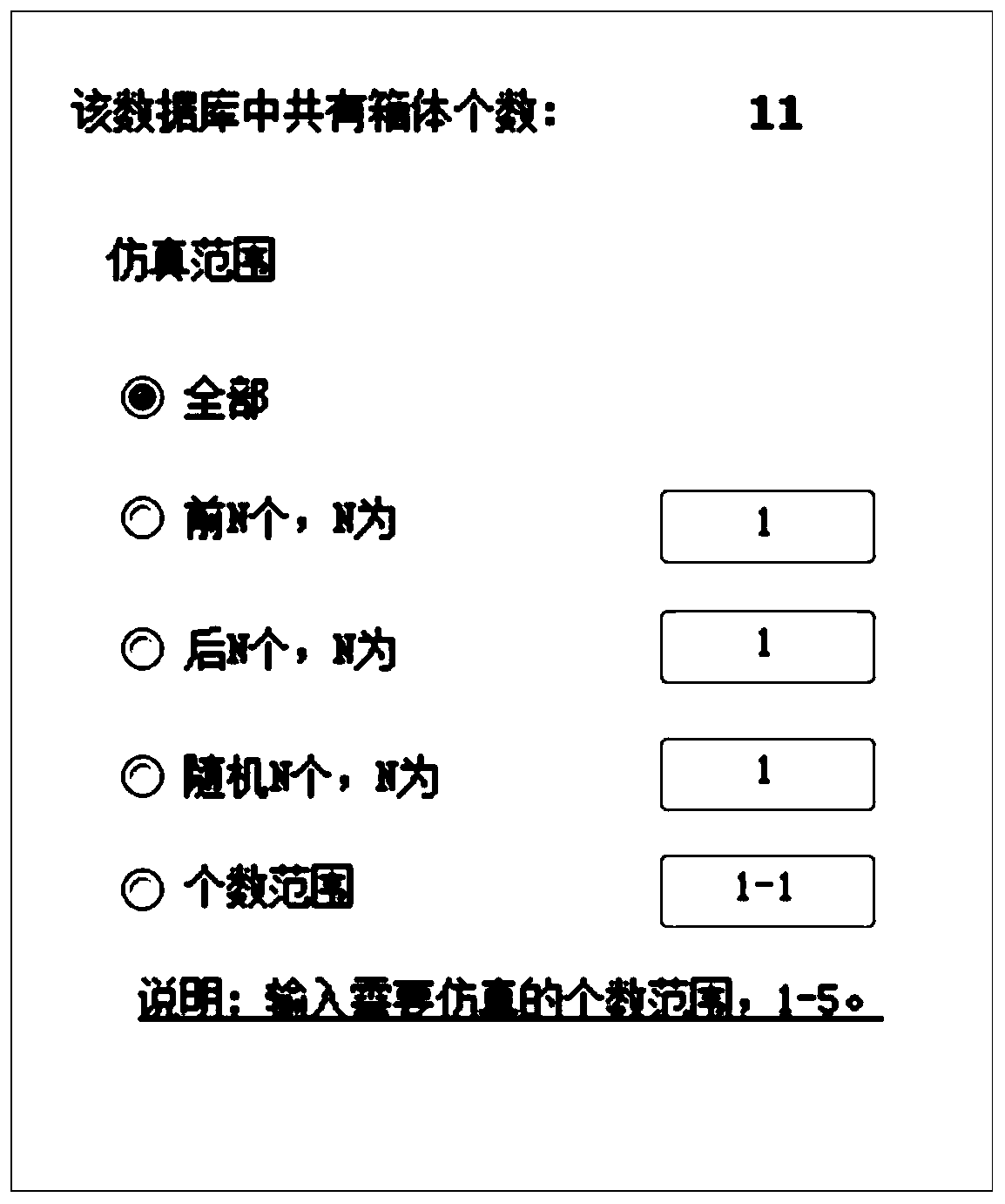
[0049] (2) Select the box to be simulated. The box can be selected arbitrarily, for example, you can choose all, multiple random, multiple in front, multiple in the back, multiple in the middle, etc., please refer to figure 2 , figure 2 A schematic diagram of the selection of a simulated box provided for the embodiment of the present invention;

[0050] (3) Read the box number and correction coefficient of each box;

[0051] (4) Set the number of cabinets in the row direction and column direction of the entire screen after the cabinets are spliced;

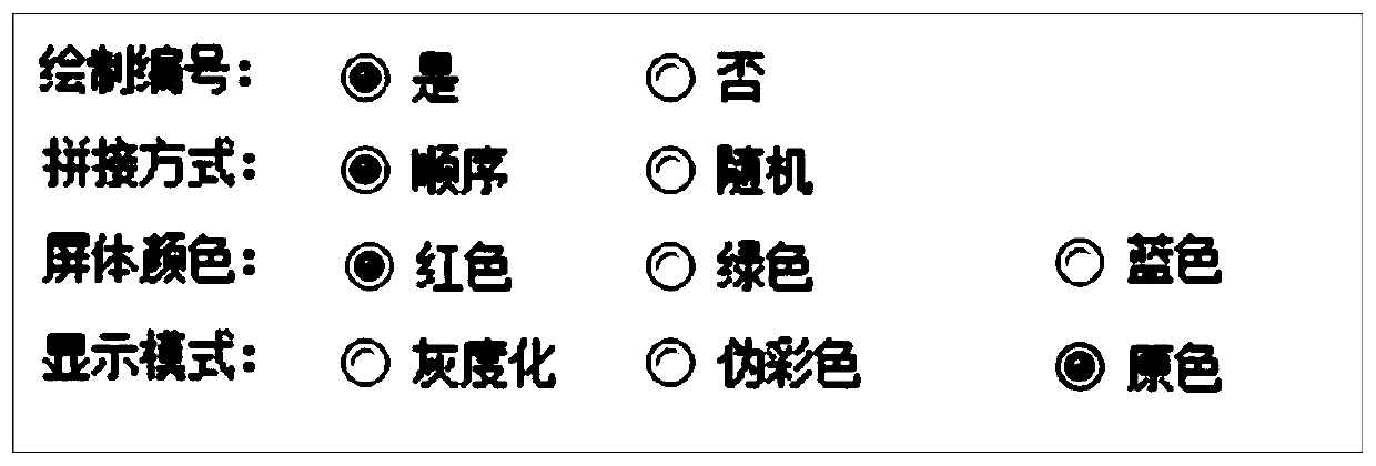
[0052] (5) To set simulation parameters, please refer to image 3 , image 3 A sc...

no. 3 example

[0064] See Figure 8 , Figure 8 It is a schematic diagram of a device for checking the effect of cabinet correction provided by the embodiment of the present invention. The device includes: a first acquisition module 001, a second acquisition module 002, a drawing module 003, a color setting module 004, a mode setting module 005 and a third acquisition module 006;

[0065] The first obtaining module 001 is used to obtain N simulated cabinets from M cabinets, where M is greater than or equal to N, and M and N are natural numbers;

[0066] The second obtaining module 002 is used to obtain the correction coefficients of the N simulated cabinets;

[0067] The drawing module 003 is used to draw a simulation diagram according to the correction coefficient and preset simulation parameters, so as to find out whether there is a problem box in the N simulation boxes based on human visual observation;

[0068] The color setting module 004 is used for setting the color of the simulati...


PUM


Abstract

The embodiment of the invention discloses a method and a device for checking correction effects of a box body. The method comprises steps of acquiring N simulation box bodies from M box bodies; acquiring correction coefficients of the N simulation box bodies; and according to the correction coefficients and a preset simulation parameter, drawing a simulation graph so that whether a defective box body exists in the N simulation box bodies can be found through visual observation of human eyes. According to the embodiment of the invention, simulation processing is performed on the correction coefficients of the corrected box bodies; brightness distribution of the box bodies before correction is simulated; correction effects of the box bodies are checked in an auxiliary manner; and splicing effects of corrected box bodies can be checked with no need to put up the boxes into the whole screen.

Description

technical field [0001] The present invention relates to the field of display technology, in particular to a method for viewing the correction effect of a cabinet and a device for viewing the correction effect of a cabinet. Background technique [0002] Today's LED display has become a mainstream information medium. In order to meet the different needs of customers, product diversification and technology are constantly being upgraded. LED display point-by-point calibration technology mainly solves the problem of poor brightness and chromaticity consistency of LED displays. With the improvement of people's display quality requirements, more and more manufacturers will perform point-by-point calibration before shipment. According to different application occasions, the point-by-point calibration technology can be divided into two types: one is box-by-box calibration on the production line (cabinet calibration); the other is on-site large-screen calibration (on-site calibration)...

Claims


Application Information

Patent Timeline
Patent Type & Authority Patents(China)
IPC IPC(8): G09G3/32
CPCG09G3/32
Inventor 郑瑞涛杨城赵星梅
Owner XIAN NOVASTAR TECH
Why Eureka
Try Eureka