
Forging forming method of cutting pick with reinforcing rib

A forging forming and reinforcing rib technology, applied in the direction of manufacturing tools, hammer driving devices, metal processing equipment, etc., can solve the problems such as the force at the bottom end of the forging head cannot be guaranteed to be exactly in the center, the forging head is inclined, and the guide sleeve is damaged. , to achieve the effect of enhancing the overall use effect, enhancing the driving force and prolonging the service life

Pending Publication Date: 2020-09-01
徐云涛
View PDF10 Cites 0 Cited by
  • Summary
  • Abstract
  • Description
  • Claims
  • Application Information

AI Technical Summary

Problems solved by technology

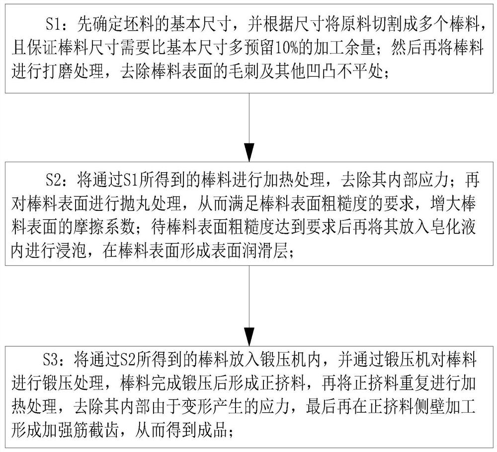
[0004] In order to make up for the deficiencies of the existing technology, to solve the problem that during the forging process, due to the shape characteristics of the product itself, the force on the bottom of the forging head cannot be guaranteed to be exactly at the center, which will cause the forging head to tilt during the forging process, causing the plunger The guide sleeve is damaged during the sliding process, resulting in the problem of "grinding". The present invention proposes a forging method for picks with reinforcing ribs

Method used


Image

  • Forging forming method of cutting pick with reinforcing rib
  • Forging forming method of cutting pick with reinforcing rib
  • Forging forming method of cutting pick with reinforcing rib

Examples


Embodiment approach

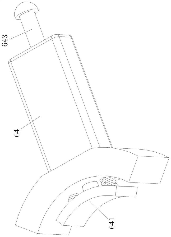
[0034] As a specific embodiment of the present invention, the second cavity 631 is provided with a wave-shaped groove 632 on the side wall close to the push rod 643; The concentrated effect of the thrust of the rod 643; when working, during the extrusion process of the clamp block 64 on the rubber pad 63, the rubber pad 63 can provide extrusion force to the push rod 643, pushing the push rod 643 to slide in the direction close to the guide post 62 , the ejector rod 643 can squeeze the friction block 641 during the sliding process, thereby strengthening the overall straightening effect of the block 64 on the guide post 62. After forming the groove 632, the deformation direction of the second cavity 631 is changed, and the gathering effect on the deformation force of the second cavity 631 is realized, thereby ensuring the effective use of the deformation force of the second cavity 631 and strengthening the overall forging press use effect.

[0035] As a specific embodiment of t...


PUM


Abstract

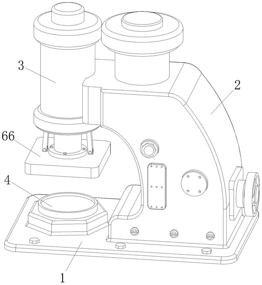
The invention belongs to the technical field of mechanical manufacturing and machining, and particularly discloses a forging forming method of a cutting pick with a reinforcing rib. A forging press adopted in the forging forming method comprises a base, a fixing frame, a stamping column, a bearing table, an air cylinder and a correcting unit; the correcting unit comprises a push plate, a guide column, a rubber pad, a clamping block, a connecting rod and a stamping head; and the push plate is installed at the output end of the air cylinder. The correction effect of the guide column is achievedthrough the matching of the base, the fixing frame, the stamping column, the bearing table, the air cylinder and the correcting unit; and when a stamping head is inclined, the connecting rod is used for exerting pressure on the clamping block, the clamping block is pushed to slide relatively far away towards the direction away from the bearing table and the direction close to the bearing table correspondingly in a first cavity, when the clamping block slides towards the direction close to the bearing table, the extrusion force of the rubber pad on the clamping block increases gradually, thus the pushing force of the guide column is enhanced by the clamping block, and the wear of a plunger on a guide sleeve in the sliding process is effectively avoided.

Description

technical field [0001] The invention belongs to the technical field of mechanical manufacturing and processing, and in particular relates to a forging forming method for picks with reinforcing ribs. Background technique [0002] Forging is a processing method that uses forging machinery to apply pressure to metal blanks to cause plastic deformation to obtain forgings with certain mechanical properties, certain shapes and sizes. It is one of the two major components of forging (forging and stamping). Forging can eliminate defects such as as-cast porosity produced in the metal smelting process and optimize the microstructure. At the same time, due to the preservation of complete metal flow lines, the mechanical properties of forgings are generally better than castings of the same material. For important parts with high loads and severe working conditions in related machinery, forgings are mostly used, except for plates, profiles or weldments that can be rolled with simpler sha...

Claims


Application Information

Patent Timeline
Patent Type & Authority Applications(China)
IPC IPC(8): B21J7/08B21J7/38B21J13/00B23P15/00
CPCB21J7/08B21J7/38B21J13/00B23P15/00
Inventor 徐云涛程顺平
Owner 徐云涛
Learn More