Cable payoff cutting device for power engineering

A cutting device and electric power engineering technology, which is applied in the direction of cable installation device, cable installation, cable laying equipment, etc., can solve the problems of unable to fix the cable, heavy winding drum, laborious and other problems, and achieve the effect of protection from damage

Active Publication Date: 2017-07-04
融创达科技成果转化(江苏)有限公司
View PDF4 Cites 18 Cited by
  • Summary
  • Abstract
  • Description
  • Claims
  • Application Information

AI Technical Summary

Problems solved by technology

[0005] In order to overcome the present invention with the development of urban construction, various enterprises, institutions and residents’ demand for communication is also increasing rapidly, the task of laying cables is increasing, and the original cable pay-off vehicle can no longer meet the construction needs. It is a difficult task to release the cable ...

Method used


Image

  • Cable payoff cutting device for power engineering
  • Cable payoff cutting device for power engineering
  • Cable payoff cutting device for power engineering

Examples


Embodiment 1

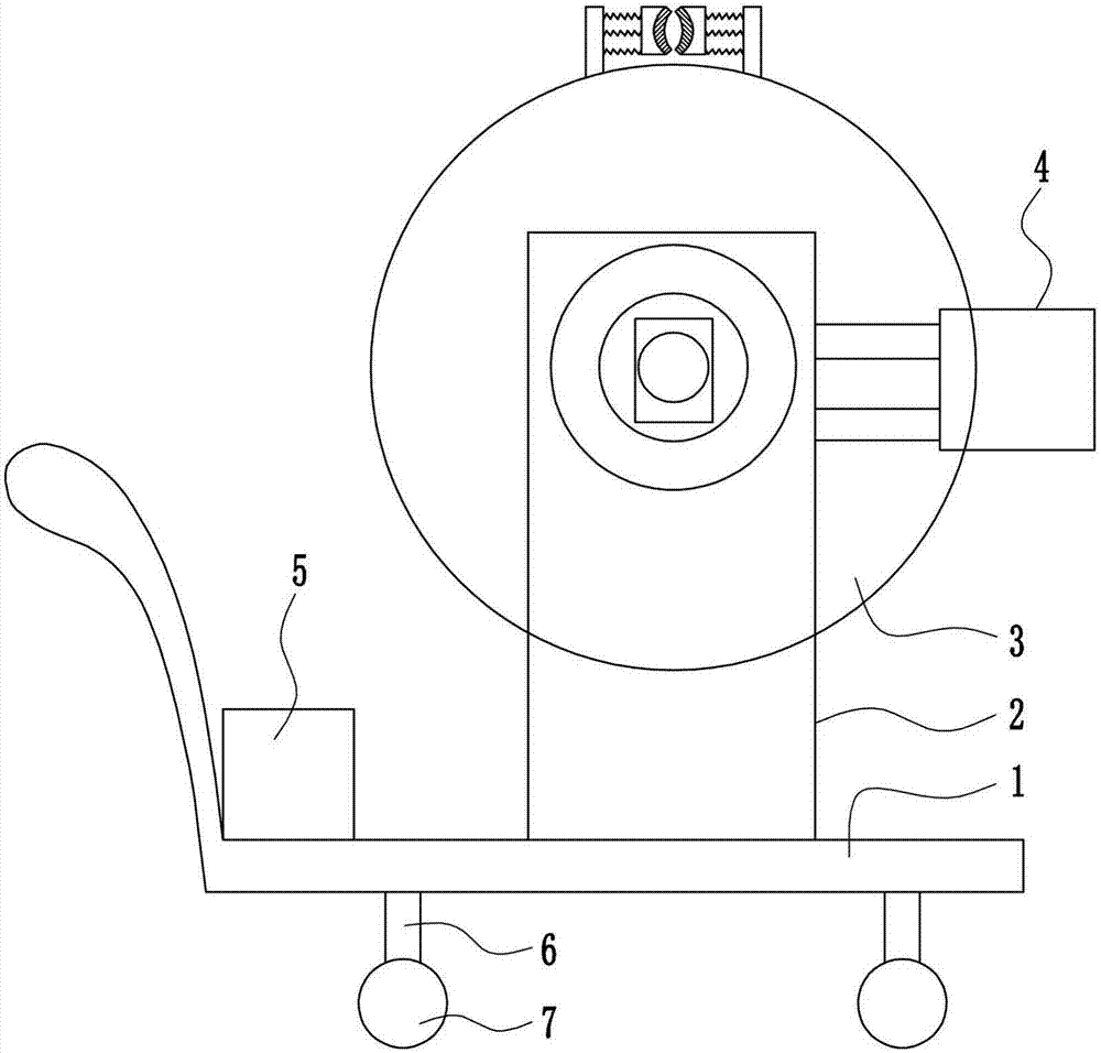
[0028] A cable pay-off and cutting device for power engineering, such as Figure 1-5 As shown, it includes a trolley 1, a mounting plate 2, a pay-off device 3, a cutting device 4, a battery 5, a pole 6 and a roller 7, and the left and right sides of the bottom of the trolley 1 are provided with a pole 6, and the bottom of the pole 6 is Rollers 7 are provided, a battery 5 is provided on the left side of the top of the cart 1, a mounting plate 2 is provided on the front and rear sides of the middle position of the top of the cart 1, and a wire release device 3 is provided between the mounting plates 2 on the front and rear sides, and the battery 5 and the pay-off device 3 are connected by wires, and a cutting device 4 is provided on the right side of the mounting plate 2 on the front side, and the cutting device 4 is located on the front side of the pay-off device 3 .

Embodiment 2

[0030] A cable pay-off and cutting device for power engineering, such as Figure 1-5 As shown, it includes a trolley 1, a mounting plate 2, a pay-off device 3, a cutting device 4, a battery 5, a pole 6 and a roller 7, and the left and right sides of the bottom of the trolley 1 are provided with a pole 6, and the bottom of the pole 6 is Rollers 7 are provided, a battery 5 is provided on the left side of the top of the cart 1, a mounting plate 2 is provided on the front and rear sides of the middle position of the top of the cart 1, and a wire release device 3 is provided between the mounting plates 2 on the front and rear sides, and the battery 5 and the pay-off device 3 are connected by wires, and a cutting device 4 is provided on the right side of the mounting plate 2 on the front side, and the cutting device 4 is located on the front side of the pay-off device 3 .

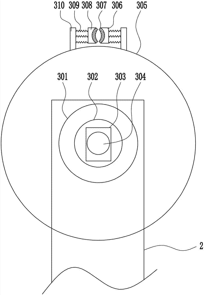
[0031]The pay-off device 3 includes a bobbin 301, a motor 302, a bearing seat 303, a rotating shaft 304, a wir...

Embodiment 3

[0033] A cable pay-off and cutting device for power engineering, such as Figure 1-5 As shown, it includes a trolley 1, a mounting plate 2, a pay-off device 3, a cutting device 4, a battery 5, a pole 6 and a roller 7, and the left and right sides of the bottom of the trolley 1 are provided with a pole 6, and the bottom of the pole 6 is Rollers 7 are provided, a battery 5 is provided on the left side of the top of the cart 1, a mounting plate 2 is provided on the front and rear sides of the middle position of the top of the cart 1, and a wire release device 3 is provided between the mounting plates 2 on the front and rear sides, and the battery 5 and the pay-off device 3 are connected by wires, and a cutting device 4 is provided on the right side of the mounting plate 2 on the front side, and the cutting device 4 is located on the front side of the pay-off device 3 .

[0034] The pay-off device 3 includes a bobbin 301, a motor 302, a bearing seat 303, a rotating shaft 304, a wi...


PUM


Abstract

The invention relates to a payoff cutting device, in particular to a cable payoff cutting device for power engineering and provides the cable payoff cutting device for the power engineering. In order to solve the technical problem, the cable payoff cutting device for the power engineering, provided by the invention, comprises a cart, wherein struts are arranged at a left side and a right side of the bottom of the cart, a roller is arranged at the bottom of each strut, a storage battery is arranged at a left side of the top of the cart, installation plates are arranged at a front side and a rear side of a middle position of the top of the cart, a payoff device is arranged between the installation plates at the front side and the rear side, the storage battery and the payoff device are connected through a wire, and a cutting device is arranged at a right side of the installation plate at the front side and is arranged at a front side of the payoff device. By the cable payoff cutting device, automatic rotation can be achieved to discharge a cable, the cable payoff cutting device is good in cable fixing effect, and the cable can be cut; and moreover, by arranging a clamping block and an anti-slip cushion, the device is better in stability.

Description

technical field [0001] The invention relates to a wire setting and cutting device, in particular to a cable setting and cutting device for electric power engineering. Background technique [0002] A cable is a wire made of one or more mutually insulated conductors and an outer insulating layer that transmits power or information from one place to another. [0003] At present, with the development of urban construction, the demand for communication of various enterprises, institutions and residents has also increased rapidly, and the task of laying cables has increased. The original cable pay-off vehicle can no longer meet the needs of construction. It is an arduous task to release the cable on the barrel, and because the winding barrel is very heavy, several people need to drag it, and the winding barrel will rotate accordingly to release the cable, which is very difficult. At the same time, the existing device cannot One end of the cable is fixed, and the cable cannot be c...

Claims


Application Information

Patent Timeline
IPC IPC(8): H02G1/06H02G1/00B65H49/32
CPCB21F11/00B65H49/32B65H49/325B65H49/34B65H2701/34H02G1/005H02G1/06
Inventor 蔡辉
Owner 融创达科技成果转化(江苏)有限公司
Why Eureka
Try Eureka