Motor Used For Motor Vehicle And Motor Vehicle

A technology of motor vehicles and rotors, applied in the direction of electromechanical devices, synchronous machines, electrical components, etc., can solve the problem of high movement costs, achieve the effect of simple movement coupling, simple cost, and increase structural cost

Active Publication Date: 2017-07-04
AUDI AG
View PDF11 Cites 3 Cited by
  • Summary
  • Abstract
  • Description
  • Claims
  • Application Information

AI Technical Summary

Problems solved by technology

However, this movement of the rotor during operation of ...

Method used


Image

  • Motor Used For Motor Vehicle And Motor Vehicle
  • Motor Used For Motor Vehicle And Motor Vehicle
  • Motor Used For Motor Vehicle And Motor Vehicle

Examples


Embodiment Construction

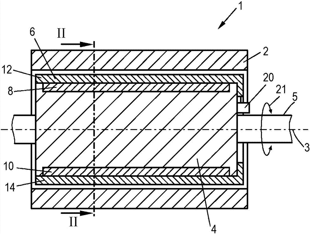
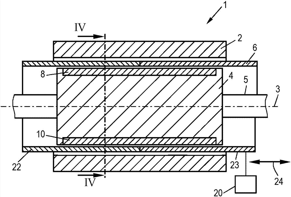
[0033] figure 1 A schematic diagram of an electric machine 1 is shown in cross section, comprising a stator 2 , a rotor 4 mounted rotatably about a rotor axis 3 , and a shaft 5 rotationally coupled to the rotor 4 . A shield 6 of cylindrical shape is arranged between the stator 2 and the rotor 4 . The electric machine 1 is designed as a permanently-magnet-excited synchronous electric machine in the form of a brushless DC motor or an electronically commutated DC motor.

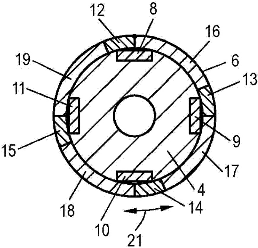
[0034] The rotor 4 has four magnetic elements 8-11 in the form of surface-mounted permanent magnets embedded in recesses, wherein, in figure 1 Magnetic elements can be seen in 8,10. The magnetic elements 8 - 10 generate two pole pairs of the magnetic excitation field of the rotor 4 .

[0035] The shield 6 is rotationally coupled to the rotor 4 and is arranged rotatably about the rotor axis 3 relative to the rotor 4 . A shield 6 is rotatably arranged on the rotor 4 at the end face of the rotor 4 . For this p...


PUM


Abstract

The present invention relates to a motor used for a motor vehicle. The motor comprises a stator 2 and a rotor 4, the rotor has at least one magnetic element 8-11 for generating a magnetic exciting field, wherein a shielding member 6 having at least one magnetic conductive conductor section is arranged between the stator 2 and the rotor 4, and the relative position of the shielding member 6 relative to the rotor can be adjusted, thereby changing a scheme that the at least one magnetic element 8-11 is covered by the at least one conductor section.

Description

technical field [0001] The invention relates to an electric machine for a motor vehicle, comprising a stator and a rotor, the rotor having at least one magnetic element generating a magnetic excitation field. Background technique [0002] Such electric machines have been known for a long time and are used in hybrid or all-electric motor vehicles in the automotive industry. Electric machines typically produce a substantially constant torque while operating at low speeds. However, at higher speeds, typically starting at around 4000 / min, the torque increases almost linearly / straight down to 0 Nm through the mutual inductive effect. [0003] It is known to overcome the torque drop by purposely weakening the field strength of the magnetic excitation field. For this purpose, the magnetic flux of the magnetic elements of the rotor can be reduced, for example, by targeted application of oppositely directed magnetic fields. The magnetic field generated for field weakening does not...

Claims


Application Information

Patent Timeline
IPC IPC(8): H02K21/02H02K1/27H02K21/14
CPCH02K1/276H02K21/028H02K21/14
Inventor J·奥贝蒂尔
Owner AUDI AG
Why Eureka
Try Eureka