
Communication device with a coil configuration for the communication with stationary data carriers

A technology of communication equipment and data carrier, which is applied in the direction of induction recording carrier, cooperative operation device, and near-field transmission system using transceivers, etc. It can solve the problems of inability to communicate, goods that cannot use communication equipment, transponders that cannot be supplied with power, etc. problems, to achieve the effect of avoiding mutual interference and reliable power

Inactive Publication Date: 2003-12-31
NXP BV
View PDF0 Cites 0 Cited by
  • Summary
  • Abstract
  • Description
  • Claims
  • Application Information

AI Technical Summary

Problems solved by technology

[0007] With known communication devices there is a problem that the communication field has a central area in which, depending on the orientation of the transponder, an unfavorable field distribution of the communication field predominates; this makes communication with the transponder virtually impossible, the transponder The communication coils of have an unfavorable orientation of the coil plane parallel to the xy-plane or parallel to the xz-plane, since in the central zone transponders with one of these orientations cannot be powered and thus cannot communicate
For goods present in packages on fixed pallets located in this central area, there is thus a problem that these goods cannot be registered fully automatically by contactless methods using communication equipment, which requires considerable additional work effort, such as repeated movement Pallets, for example or require considerable construction costs, such as supplies like transferable coil arrangements, or conveyor belts for moving the pallets

Method used


Image

  • Communication device with a coil configuration for the communication with stationary data carriers
  • Communication device with a coil configuration for the communication with stationary data carriers
  • Communication device with a coil configuration for the communication with stationary data carriers

Examples


Embodiment Construction

[0032] Detailed description of preferred embodiments

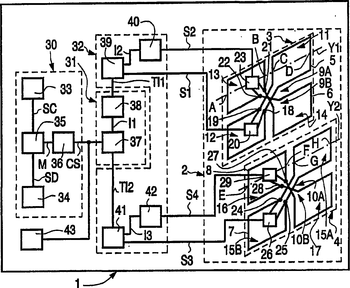
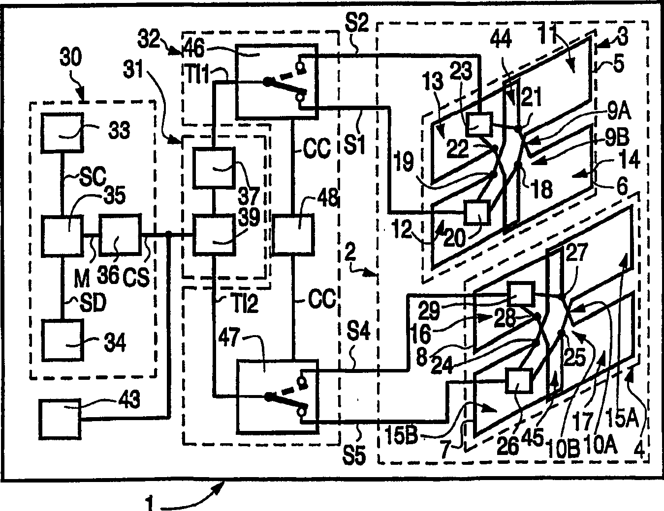
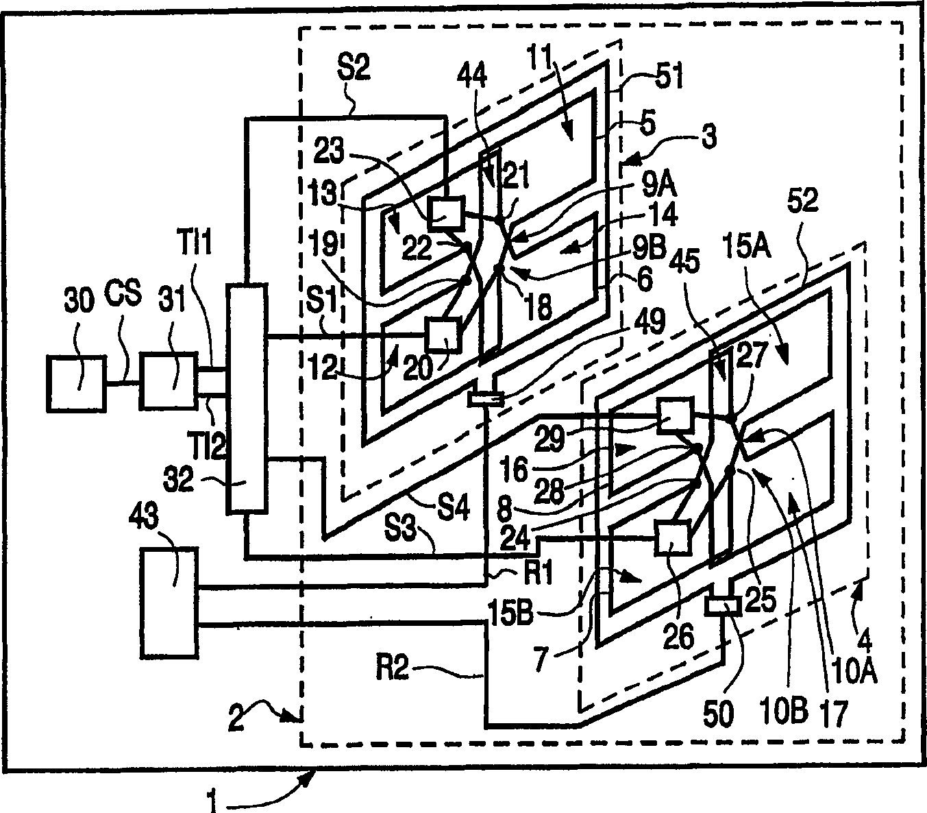
[0033] figure 1 Represents a communication device 1 which is designed to communicate with at least one data carrier that can be introduced into the communication field of the communication device. The communication device 1 forms a so-called "scanning station". The data carrier is used for the fully automatic registration of the goods and is packed into the package of the packaged goods. The package is placed on a pallet. For the fully automatic registration of goods, the pallet is placed in the communication area of ​​the channel and the data carrier remains fixed here during the communication. For communication, the communication device 1 has a coil configuration 2, which has a first sub configuration 3 and a second sub configuration 4 opposite to the first sub configuration 3. Through the two sub configurations 3 and 4, the two sub configurations 3 and 4 can be generated. 4 operable communication field between. It should ...


PUM


Abstract

In the communication device (1), there is firstly a coil configuration (2) with two oppositely placed sub-configurations (3, 4) through which a gap between the two sub-configurations (3, 4) can be generated. An operating communication field, and each of the two sub-configurations (3, 4) has at least two coils (5, 6, 7, 8), the communication device also has a sub-configuration signal generating device (31) designed to In order to be able to differentially generate and transmit a first sub-configuration signal (TI1) and a second sub-configuration signal (TI2) for each of the two sub-configurations (3, 4), the communication device is also provided with coil signal generating means (32 ), which is designed to differentially generate and transmit coil signals for at least two coils (5, 6, 7, 8) of each subconfiguration (3, 4) based on the respective subconfiguration signal (TI1, TI2) (S1, S2, S3, S4).

Description

Invention field [0001] The present invention relates to a communication device that communicates with at least one data carrier, said data carrier being able to be introduced into the communication field of the communication device, and the communication device has a coil configuration with two relative sub-configurations, through which The configuration is capable of generating a communication field operating between two sub-configurations, and the communication device has a sub-configuration signal generating device, which is designed to distinguishably generate and transmit a first sub-configuration signal for corresponding one of the two sub-configurations And the second sub-configuration signal. [0002] The present invention also relates to a coil configuration for communicating with at least one data carrier, which data carrier can be introduced into a communication field generated with said coil configuration, said coil configuration having two opposite sub-configurations,...

Claims


Application Information

Patent Timeline
Patent Type & Authority Applications(China)
IPC IPC(8): G06K17/00G06K7/08G06K7/10H04B1/59H04B5/00H04B5/02
CPCG06K7/10336G06K7/10346H04B5/0087H04B5/263
Inventor P·拉加姆
Owner NXP BV
Learn More