Control and power distribution system for a conveyor

a technology of control and power distribution system, which is applied in the direction of rolling-way, instruments, computing, etc., can solve the problems of increasing the total cost of construction and assembly, and the need for extensive troubleshooting time for conventional conveyors, so as to reduce the number of power drops, and reduce the cos

Inactive Publication Date: 2006-09-12
LOCKHEED MARTIN CORP
View PDF11 Cites 25 Cited by
  • Summary
  • Abstract
  • Description
  • Claims
  • Application Information

AI Technical Summary

Benefits of technology

[0003]A conveyor in accordance with the present invention is controlled and powered efficiently, economically, and reliably. The conveyor combines the control and power components of up to sixteen 30-inch zones into one enclosure or panel. Each panel distributes I / O and 24 VAC power locally with source power (i.e., 480 VAC) and field bus communication distributed regionally. Thus, power is distributed with low line loss and lower gauge wiring by local power supplies, which may efficiently convert power to 24V for local I / O.
[0004]The conveyor in accordance with the present invention defines a system that is packaged to reduce total cost of ownership. With modular cables and one-size-for-all panels, less engineering for each site installation is required. Fewer components are necessary to procure and spare. Installation only requires the mating up of keyed connectors at the panels and I / O points, which may be performed quickly with the lowest level of skilled labor. Field integration testing may also be reduced since the cables and panel are tested at assembly, typically off site. Further, maintenance may be reduced with fewer non-standard, pre-fabricated replacement parts.
[0006]Each control panel includes quick disconnect bulkhead connectors, 16 input-16 output I / O modules, a field bus communications adapter, and a power supply in a safe enclosure. The panel protects personnel from potential hazards of contact with the supply side of the power source. Each panel may be field mounted based on pre-punched holes to a conveyor rail and corresponding mating flanges on each panel. The panel door may have a disconnect to isolate personnel from power when the panel door is open. The disconnect may be overridden for integration and maintenance operations. Fuses in each panel may protect downstream components.
[0008]Additionally, a panel may have a field bus communications adaptor attached to it for one of several open buses such as Device Net, Interbus, Profibus, or Ethernet. The field bus protocol typically communicates with a bus master card in the controller. The card preferably communicates via an Object Linking and Embedding for Process Control (OPC) compliant interface to a software application, such as Think & Do Studio by Entivity. The software application manages the flow of product across the conveyor utilizing logic driven by I / O information. Thus, the logic loaded into multiple PLC's in prior art systems may be centrally located in the controller. This reduces development, installation, and support effort while creating a single point of contact for management level information systems.
[0009]The system in accordance with the present invention reduces the number of power drops, individual power supply points, and communication nodes (i.e., distributed Input / Output modules). Rather than a field bus node in every zone or one per conveyor section, up to sixteen zones are combined into a single control panel through cables. Field wiring is replaced by quick disconnect cables. Pre-wired and pre-tested control panels eliminate field wiring. The wiring is less expensive because it is standardized and made in bulk. A larger single power supply driving DC loads in both directions reduces the number of individual power supplies per section of conveyor. The system further allows significant reduction of the total number of connectors and terminations per installation.

Problems solved by technology

Custom components and field wiring of power drops by electricians increase the total cost of construction and assembly.
If a section unseats during installation or normal use, the conventional conveyor requires extensive debug time to trouble-shoot.

Method used


Image

  • Control and power distribution system for a conveyor
  • Control and power distribution system for a conveyor
  • Control and power distribution system for a conveyor

Examples


Embodiment Construction

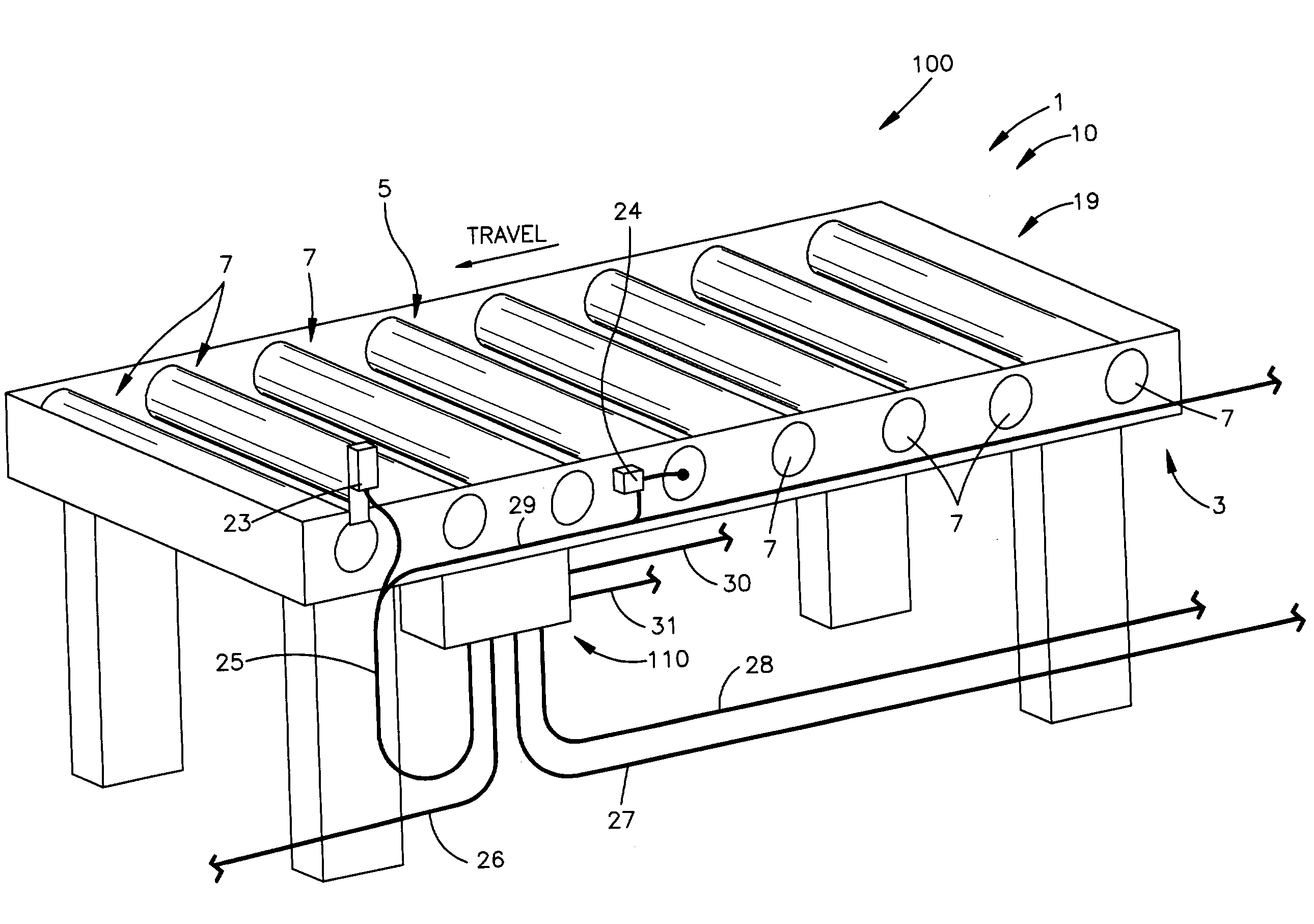
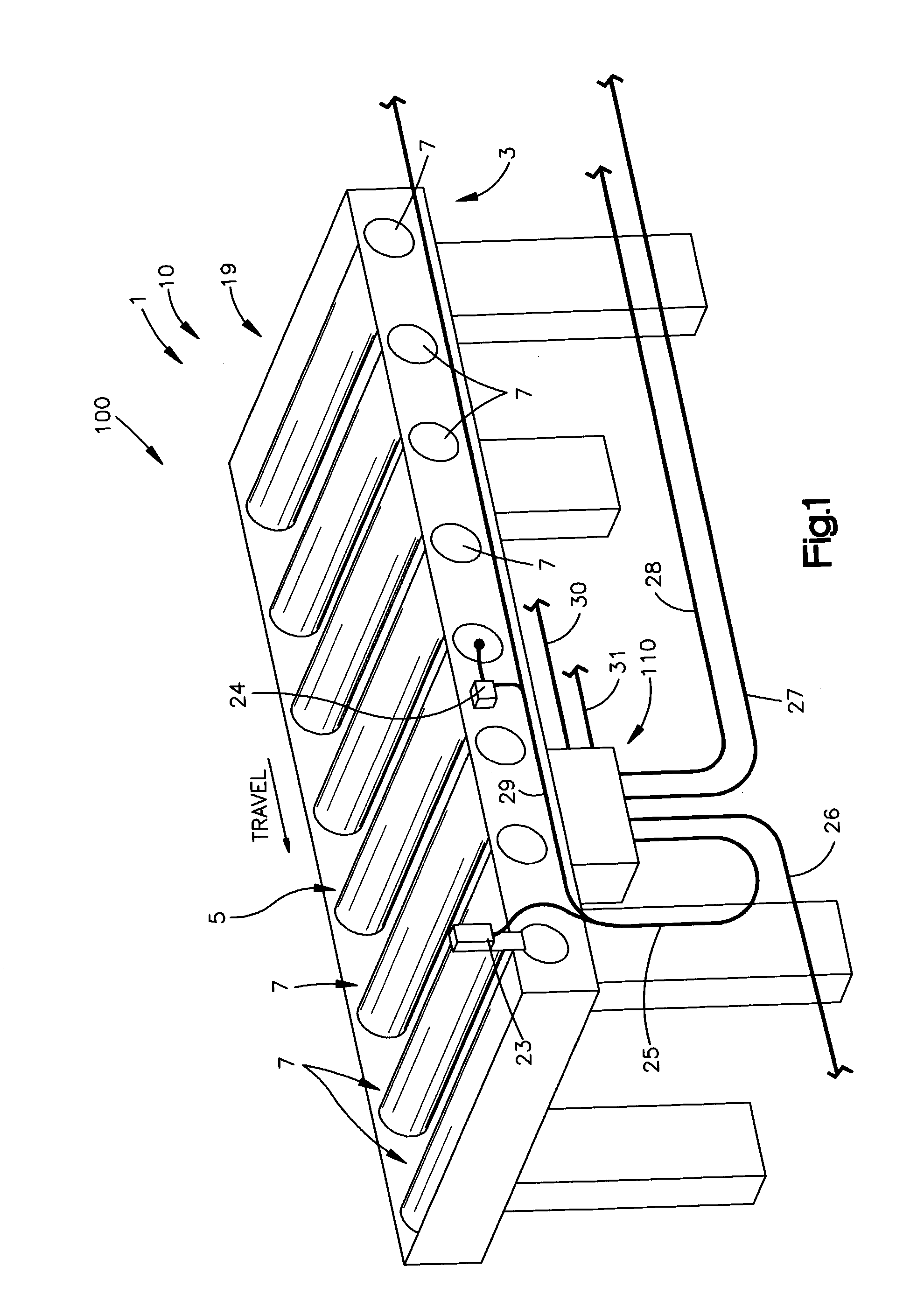
[0013]A system 100 (as illustrated schematically in FIGS. 1 and 2) in accordance with the present invention controls and powers a conveyor 1. An example accumulation conveyor 1 for use with the system 100 may use electrical sensors, motor driver cards, and a power roller. Each section 10 of the example conveyor 1 is linked to three adjacent sections 10 (not shown). A network of control / power panels 110, each controlling and powering groups of four sections 10, and a controller 120 interact to control and power the entire conveyor 1.

[0014]As illustrated schematically in FIGS. 1 and 2, a 30″ zone 19 of a section 10 of the conveyor 1 may include a photo-eye sensor 23 and a motor driver card 24 powered by a 24 VDC power supply panel 110. Therefore, four zones 19 may correspond to four inputs (i.e., photo-eye sensors 23) and four outputs (i.e., motor driver cards 24) in the panel 110, plus 24 VDC power distribution from a power supply.

[0015]The control and power distribution system 100 i...


PUM


Abstract

A conveyor conveys objects. The conveyor includes a plurality of sections, a first control panel, and a second control panel. The plurality of sections define the structure of the conveyor. Each of the plurality of sections has components for controlling the mechanical operation of each section. The controller controls and powers the conveyor. The first control panel provides control and power to a first group of four of the plurality of sections. The first control panel provides power to the components of the first group. The second control panel provides control and power to a second group of four of the plurality of sections. The second control panel provides power to the components of the second group. The modular interconnectivity components interconnect the controller, the first control panel, the second control panel, the first group, and the second group. The controller provide control and power to the first control panel and the second control panel.

Description

TECHNICAL FIELD[0001]The present invention relates to a power roller conveyor and, more particularly, to a control and power distribution system for a power roller conveyor.BACKGROUND OF THE INVENTION[0002]A conventional power roller conveyor typically has pre-wired controls in side rails and includes a power supply in each section. Custom components and field wiring of power drops by electricians increase the total cost of construction and assembly. For modularity, each section of the conventional conveyor has power and control connectors that mate with the sections upstream and downstream of it. If a section unseats during installation or normal use, the conventional conveyor requires extensive debug time to trouble-shoot.SUMMARY OF THE INVENTION[0003]A conveyor in accordance with the present invention is controlled and powered efficiently, economically, and reliably. The conveyor combines the control and power components of up to sixteen 30-inch zones into one enclosure or panel....

Claims


Application Information

Patent Timeline
Patent Type & Authority Patents(United States)
IPC IPC(8): B65G13/06B65G43/10
CPCB65G43/10B65G13/06
Inventor BROWN, THOMAS M.DESANTO, ANTHONY J.LOCKE, GARY J.
Owner LOCKHEED MARTIN CORP
Why Eureka
Try Eureka