Unidirectional coupling damping pulley

a technology of unidirectional coupling and pulley, which is applied in the direction of couplings, hoisting equipments, mechanical devices, etc., can solve the problems of shortening the service life of the pulley, overloading the belt, and excessive torque and tension of the pulley, so as to improve the service life and reliability of the power transmission. , the effect of simple structur

Active Publication Date: 2015-06-18
LI ZHIMIN
View PDF5 Cites 23 Cited by
  • Summary
  • Abstract
  • Description
  • Claims
  • Application Information

AI Technical Summary

Benefits of technology

[0021]The unidirectional coupling damping pulley using spring friction for braking disclosed in the present invention has advantages, such as ...

Problems solved by technology

When a generator is driven by a crankshaft of an automotive engine via a belt, a pulley unit, etc., excessive torque and tension may be exerted on the pulley, the rotating shaft (the axle) and the pulley as a result of cycling of induction, compression, combustion and expansion, and exhaust strokes.
When the rotation of the crankshaft suddenly decelerates, since the rotating shaft of the generator has a large inertia, the belt is pulled in the direction of torque rotation producing a change in the tension, which may result in overload of the belt and thereby shortening its service life.
Howeve...

Method used


Image

  • Unidirectional coupling damping pulley
  • Unidirectional coupling damping pulley
  • Unidirectional coupling damping pulley

Examples


embodiment 1

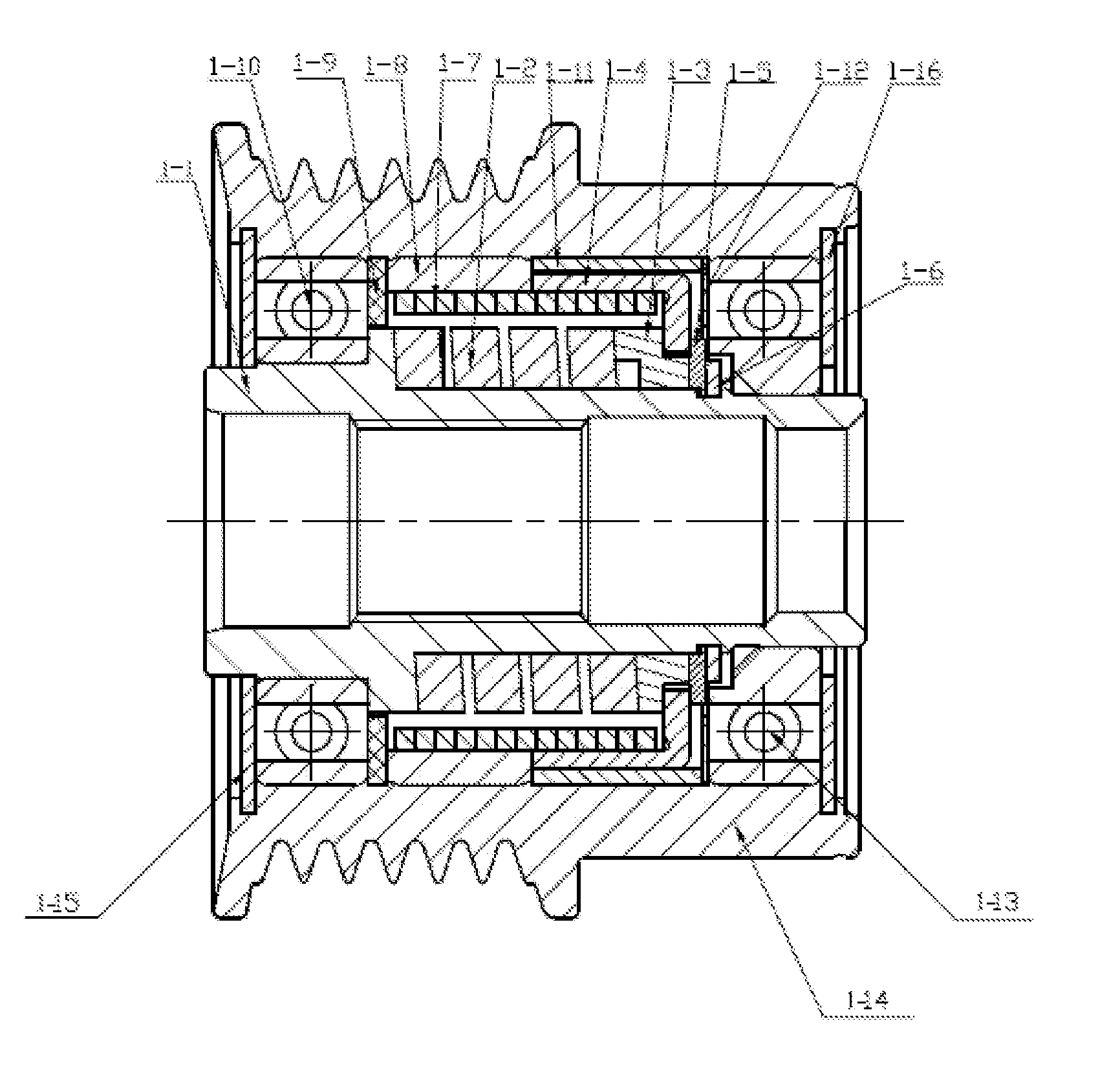
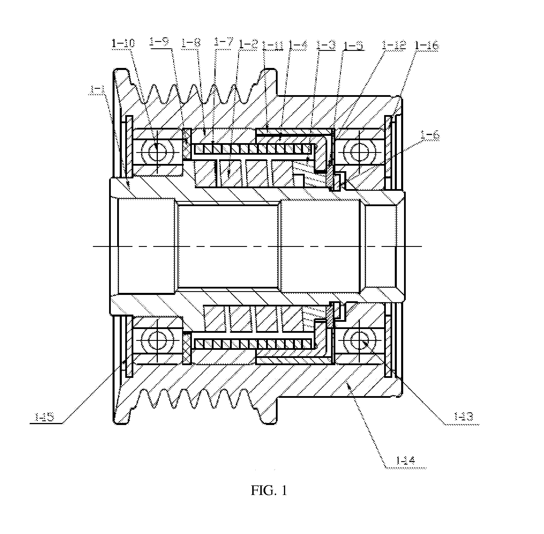
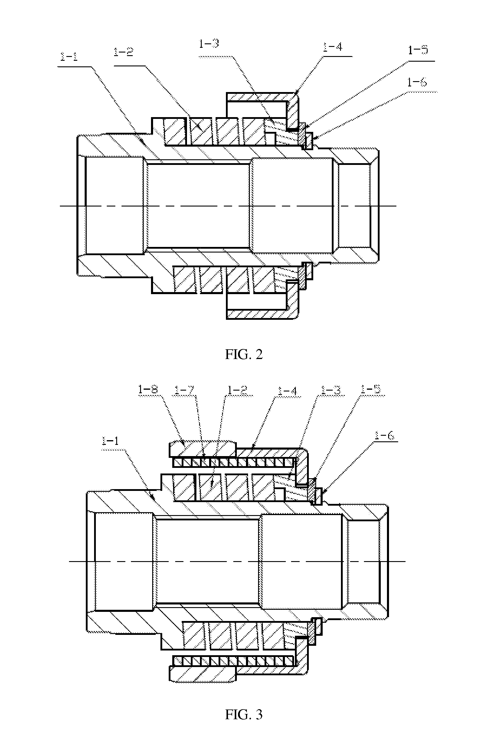
[0058]As shown in FIGS. 1-19, a unidirectional coupling damping pulley using spring friction for braking in the present embodiment comprises a threaded core shaft 1-1, a damping spring 1-2, a damping washer 1-3, a friction sliding ring 1-4, a washer 1-5, a square wire snap ring 1-6, a friction spring 1-7, a friction stopper ring 1-8, an anterior retaining ring 1-9, an anterior ball bearing 1-10, a positioning sleeve 1-11, a posterior retaining ring 1-12, a posterior ball bearing 1-13, a pulley hub 1-14, an anterior dust-proof washer 1-15, and a posterior dust-proof washer 1-16.

[0059]A damping spring mechanism is arranged in an inner bore of the pulley hub 1-14. The damping spring mechanism comprises a threaded core shaft 1-1, a damping spring 1-2, a damping washer 1-3, a friction moving sleeve 1-4, a washer 1-5, a square wire snap ring 1-6. A protruding ring 1-1-6 with a helicoid surface is formed on one end of the outer diameter 1-1-1 of the threaded core shaft 1-1. The helicoid su...

embodiment 2

[0069]As shown in FIGS. 20-34, a unidirectional pulley using spring friction clutch for braking in the present embodiment comprises a threaded core shaft 2-1, ball bearings 2-2, retaining rings 2-3, a friction spring 2-4, a friction stopper ring 2-5, a friction sliding ring 2-6, a positioning sleeve 2-7, a positioning washer 2-8, a pulley hub 2-9, and dust-proof washers 2-10.

[0070]A spring friction clutch mechanism is arranged in the pulley hub 2-9. The mechanism comprises a friction spring 2-4, a friction stopper ring 2-5, a friction sliding ring 2-6. See FIG. 21. The friction stopper ring 2-5 is the shape of a circular ring. A portion of the friction sliding ring 2-6 is in the shape of a circular ring, and the other portion of the friction sliding ring is bent inwards by 90 degrees and provided with a through bore. The shape of the bore is a circle with two opposite bow-like segments removed. The inner edge of each segment is a plane 2-6-1. The inner diameter of the friction stopp...


PUM


Abstract

A unidirectional coupling damping pulley includes a threaded central spindle extending into a pulley hub, a friction stopper ring and a positioning sleeve pressed against the inner wall of the pulley hub, a protruding ring formed on the outer diameter of the central spindle, in which the central spindle is sleeved with a damping washer forming a step on one side of the damping washer, the central spindle is sleeved with a damping spring the damping washer is sleeved and in rotation fit with a friction sliding ring, a friction spring is sleeved around the damping spring the friction spring locks up with the friction stopper ring and the friction sliding ring through friction, and the friction spring can be separated from the friction stopper ring and the friction sliding ring alternately.

Description

TECHNICAL FIELD[0001]The present invention relates to the technical field of the manufacture of unidirectional coupling damping pulley used for automobile generators, particularly a unidirectional coupling damping mechanism using spring friction for braking, specifically a unidirectional coupling damping pulley using spring friction for braking.BACKGROUND[0002]Unidirectional clutch pulleys of automobile alternators (generators) have been widely used in some high-end automobiles all over the world. When a generator is driven by a crankshaft of an automotive engine via a belt, a pulley unit, etc., excessive torque and tension may be exerted on the pulley, the rotating shaft (the axle) and the pulley as a result of cycling of induction, compression, combustion and expansion, and exhaust strokes. When the rotation of the crankshaft suddenly decelerates, since the rotating shaft of the generator has a large inertia, the belt is pulled in the direction of torque rotation producing a chang...

Claims


Application Information

Patent Timeline
IPC IPC(8): F16H55/36
CPCF16H55/36F16H2055/366F16D3/12F16D41/206
Inventor LI, ZHIMIN
Owner LI ZHIMIN
Why Eureka
Try Eureka