Speed reducer

a technology of speed reducer and gear reduction, which is applied in the direction of gearing, hoisting equipment, instruments, etc., can solve the problems of frequent damage of machine parts, weak coupling degree, and inability to guarantee smooth power transmission, so as to reduce the total size of the reduction gear and reduce the manufacturing cost.

Inactive Publication Date: 2014-07-31
YOON EUNSEOK
View PDF6 Cites 23 Cited by
  • Summary
  • Abstract
  • Description
  • Claims
  • Application Information

AI Technical Summary

Benefits of technology

[0032]Furthermore, the speed reducer according to the present invention can minimize the total size of the reduction gear, thereby resulting in the reduction of the manufacturing cost. Furthermore, the speed reducer according to the present invention can be applied in various fields that require miniaturization and refinement.

Problems solved by technology

However, in the conventional speed reducer as described above, the output shaft of the speed reducer is coupled with the ring gear shaft by means of the pin so that the degree of coupling is not strong.
Accordingly, it does not guarantee a smooth power transmission.
Furthermore, when the speed reducer is operated for a long time, then the pin, the ring gear shaft and the output shaft, etc. cannot stand the rotational force and thereby resulting in frequent damage of these machine parts.
As a result, it causes a failure of the reduction gear.
Likewise, these ring gear and the ring gear shaft may be easily and frequently damaged due to the rotation force while the speed reducer is operated for a long time.
This leads to occurrence of excessive maintenance costs for the speed reducer.
Meanwhile, since a rotational force may be transmitted through the output shaft of a one end of the driving shaft in the conventional speed reducer, the efficiency of power transfer is limited.
Furthermore, in the conventional speed reducer, since the output shaft is not rigidly fixed, the fluctuations and the uneven wear of the output shaft was terribly occurred, and thereby resulting in the limitation of the transfer of minute rotational force.
Since most of the mechanical constitution is very complicate and the overall volume is large, it is hard to use in a system that requires a precise control such as joints of the robot and this leads to occurrence of excessive manufacturing costs.

Method used


Image

  • Speed reducer
  • Speed reducer
  • Speed reducer

Examples


first embodiment

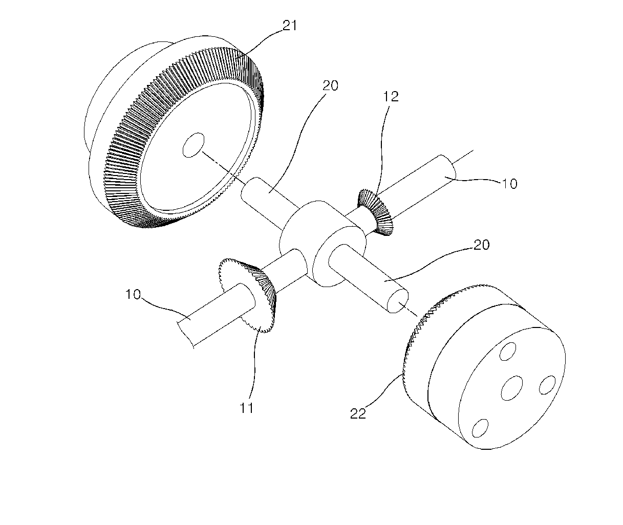
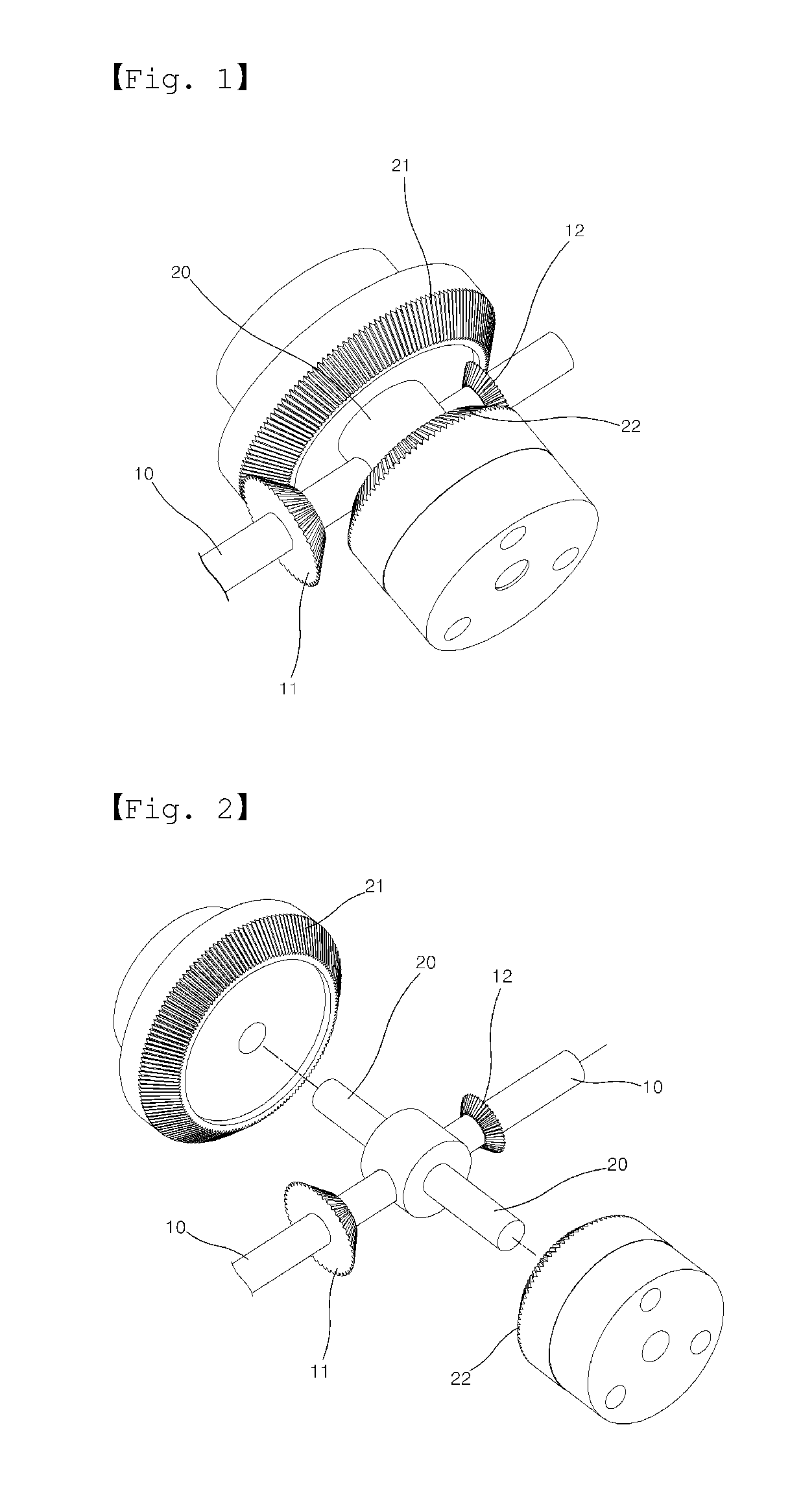
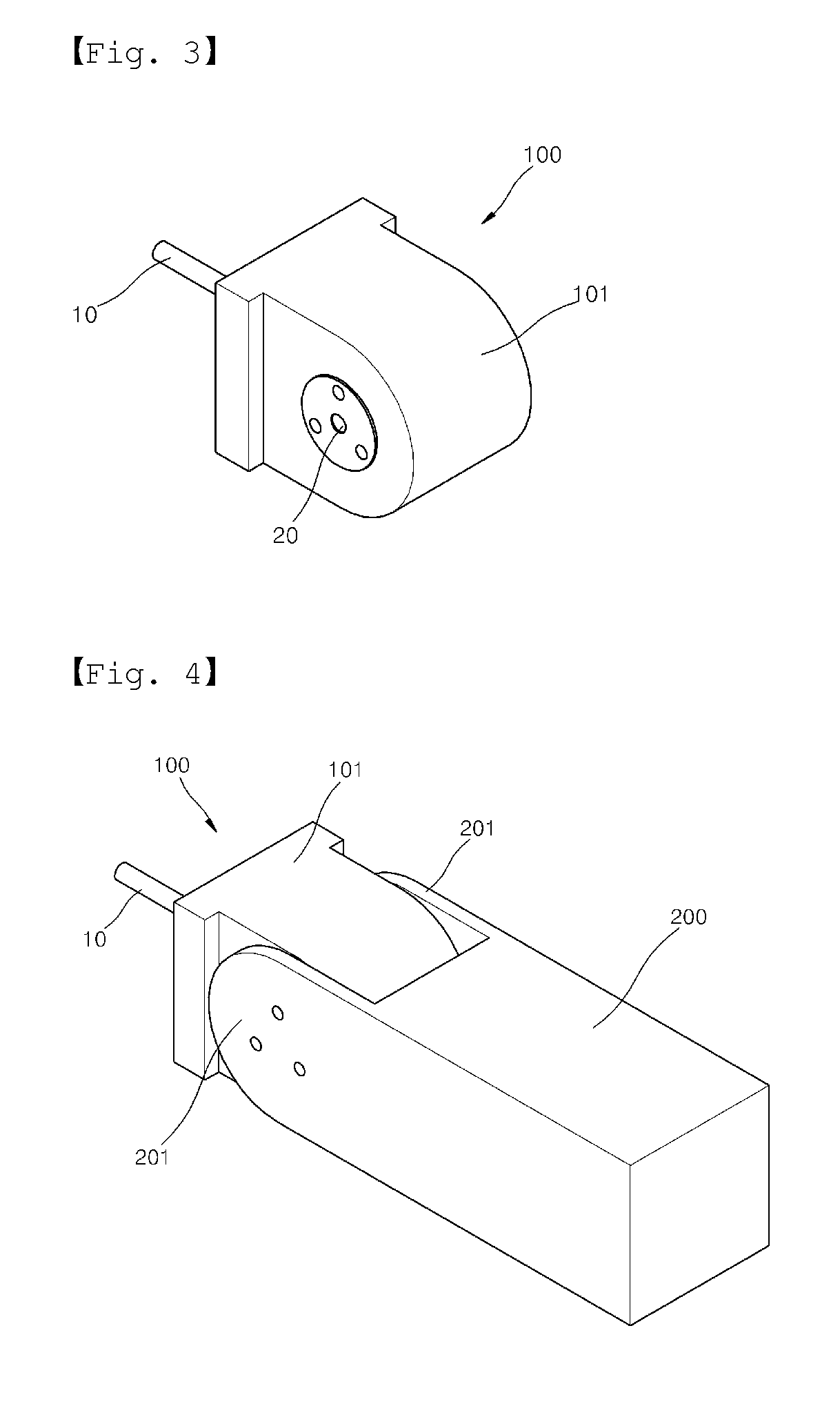
[0059]FIG. 1 is an exterior perspective view of a speed reducer according to a preferred first embodiment of the present invention, FIG. 2 is an exploded perspective view of the speed reducer as illustrated in FIG. 1, FIG. 3 shows an external appearance of the speed reducer as illustrated in FIG. 1, and FIG. 4 shows an application state that the speed reducer as illustrated in FIG. 1 is installed at a robot joint.

[0060]Referring to FIGS. 1 to 4, the speed reducer comprises a driving gear installed at a one end of a driving shaft 10 which rotates by receiving a driving force from a driving means such as a motor, an engine, etc. The speed reducer further comprises a driven gear for changing the direction of the rotational force of the driving gear into a direction perpendicular to the original direction. The driven gear is installed to the driving gear. As shown in the attached drawings FIG. 1 to FIG. 4, the driving gear and the driven gear comprises a bevel gear.

[0061]The driving gea...

second embodiment

[0077]FIGS. 10 to 14 show the speed reducer according to a preferred second embodiment of the present invention. FIG. 10 is an exterior perspective view of the speed reducer, FIG. 11 is an exploded perspective view of the speed reducer as illustrated in FIG. 10, and FIG. 12 is a partial side sectional view of the speed reducer and the robot joint.

[0078]Referring to FIGS. 10 to 12, the speed reducer according to the preferred second embodiment of the present invention has the same configuration as that of the first embodiment. In other words, the speed reducer according to the preferred second embodiment of the present invention comprises the first driving gear 11 and the second driving gear 12 which comprise a bevel gear, respectively and are installed on the driving shaft 10 in a state that they are opposite to each other; the first driven gear 21 and the driven gear 22 which are installed on the driven shaft in a state that they are opposite to each other and they can be meshed wi...

third embodiment

[0083]FIGS. 15 to 18 show the speed reducer according to a preferred third embodiment of the present invention. FIG. 15 is an exterior perspective view of the speed reducer, FIG. 16 is an exterior perspective view of the speed reducer, for showing a state that a fluctuation prevention means is installed at the speed reducer, FIG. 17 shows an external appearance of the speed reducer installed within a case, and FIG. 18 is an exterior perspective view of the speed reducer and the robot joint, for showing the application state that the speed reducer is installed at the robot joint.

[0084]Referring to FIGS. 15 to 18, the speed reducer according to the preferred third embodiment of the present invention has the same configuration as that of the first embodiment.

[0085]In other words, the speed reducer according to the preferred third embodiment of the present invention comprises the first driving gear 11 and the second driving gear 12 which comprise a bevel gear, respectively and are insta...


PUM


Abstract

Disclosed is a speed reducer capable of precisely and reliably maintaining a rotational force of the output shaft and of maximizing its efficiency by allowing the rotational force of the driving shaft to transmit and to slow down via a plurality of bevel gears and by preventing the fluctuation of the output shaft so as to prevent uneven wear due to the long working and to prevent the damage due to the fluctuation. The speed reducer comprises a pair of driving gears 11,12 installed at a one end of a driving shaft 10 driven by a driving means, a pair of driven gears 21,22 meshed with the driving gear 11,21 and a rotational member 200 for outputting the rotational force to slow down, in which the driven gears 21,22 comprise a bevel gear, respectively and the rotational member 200 is coupled to the driven gears 21,22.

Description

BACKGROUND OF THE INVENTION[0001]1. Field of the Invention[0002]The present invention relates generally to a speed reducer having a simple configuration, which is capable of precisely and reliably delivering the power to slow down.[0003]2. Description of the Prior Art[0004]Generally, the speed reducer which has been conventionally widely used in related industries includes a pinion shaft that receives a power of the motor, a reduction gear that is integrally coupled to a one side of the pinion shaft, a ring gear meshing and rotating with the reduction gear, and a ring gear shaft for inducing the transmitted power to a drive shaft, the ring gear shaft having a pin hole in which a pin is inserted so as to fix the ring gear shaft into the ring gear.[0005]However, in the conventional speed reducer as described above, the output shaft of the speed reducer is coupled with the ring gear shaft by means of the pin so that the degree of coupling is not strong. Accordingly, it does not guarant...

Claims


Application Information

Patent Timeline
Patent Type & Authority Applications(United States)
IPC IPC(8): F16H1/20F16H1/28
CPCF16H1/203F16H1/28B25J9/1025F16H49/001B25J9/102F16H1/14F16H37/041F16H1/16Y10T74/19688Y10T74/19828Y10T74/19642G08G1/095F16L19/02F16L15/00E04H12/00
Inventor YOON, EUNSEOK
Owner YOON EUNSEOK
Why Eureka
Try Eureka