
Measurement method and device for cardiac blood flow speed of magnetic resonance

A technology of heart blood flow and measurement method, which is applied in the field of medical information, can solve the problem of reducing image time resolution, achieve the effect of improving time resolution, shortening the required time, and accurately measuring heart blood flow velocity

Active Publication Date: 2017-07-07
SHENZHEN INST OF ADVANCED TECH CHINESE ACAD OF SCI
View PDF1 Cites 4 Cited by
  • Summary
  • Abstract
  • Description
  • Claims
  • Application Information

AI Technical Summary

Problems solved by technology

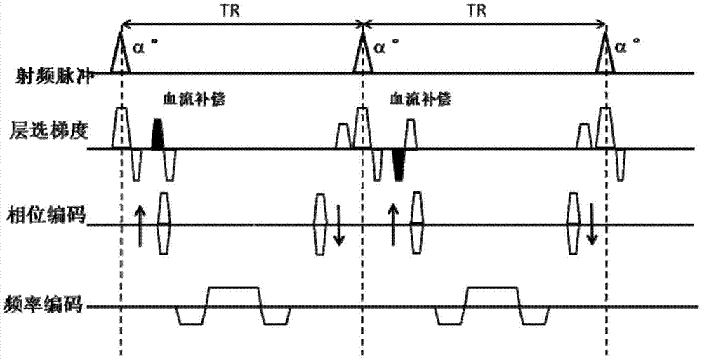
[0005] In view of this, an embodiment of the present invention provides a method and device for measuring blood flow velocity of the magnetic resonance heart to solve the problem of measuring the blood flow velocity by magnetic resonance cardiac blood flow imaging technology provided in the prior art. In each TR, only Collecting a line and collecting the entire image requires multiple TRs to complete, which greatly reduces the time resolution of the image

Method used


Image

  • Measurement method and device for cardiac blood flow speed of magnetic resonance
  • Measurement method and device for cardiac blood flow speed of magnetic resonance
  • Measurement method and device for cardiac blood flow speed of magnetic resonance

Examples


Embodiment 1

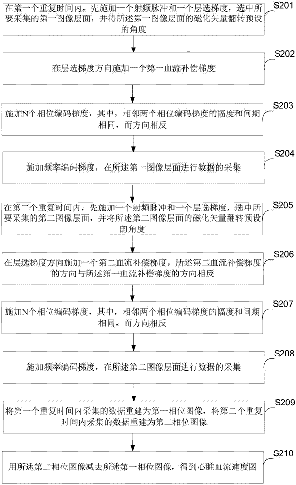
[0045] figure 2 The implementation process of the magnetic resonance cardiac blood flow velocity measurement method provided in the first embodiment of the present invention is shown, and the details are as follows:

[0046] In step S201, within the first repetition time, a radio frequency pulse and a slice selection gradient are firstly applied, the first image slice to be collected is selected, and the magnetization vector of the first image slice is flipped by a preset angle.

[0047] In the embodiment of the present invention, the selection of the image slice and slice thickness is accomplished by controlling the radio frequency pulse and slice selection gradient.

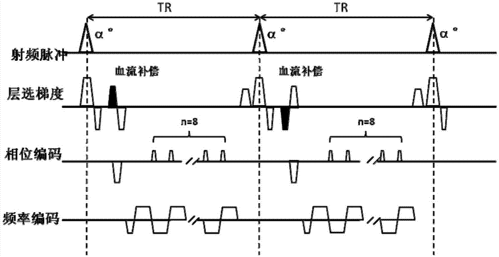
[0048] like image 3 As shown, firstly, in the first repetition time, a radio frequency pulse and a slice selection gradient are applied, the first image slice to be acquired is selected, and then the magnetization vector of the first image slice is flipped by α°.

[0049] Wherein, the first image slice is o...

Embodiment 2

[0076] Figure 4 A specific structural block diagram of the device for measuring the magnetic resonance cardiac blood flow velocity provided in the second embodiment of the present invention is shown. For convenience of description, only the parts related to the embodiment of the present invention are shown. The magnetic resonance cardiac blood flow velocity measurement device 4 includes: a first gradient application module 41, a second gradient application module 42, a third gradient application module 43, a fourth gradient application module 44, a fifth gradient application module 45, a sixth A gradient application module 46 , a seventh gradient application module 47 , an eighth gradient application module 48 , a data reconstruction module 49 and a blood flow velocity acquisition module 410 .

[0077] Among them, the first gradient application module 41 is used for firstly applying a radio frequency pulse and a layer selection gradient within the first repetition time, selec...


PUM


Abstract

The invention belongs to the technical field of medical information and provides a measurement method and device for cardiac blood flow speed of magnetic resonance. The method comprises the following steps: firstly applying radio frequency pulse and a layer gradient within the first repetition time; applying a first blood flow compensation gradient in a layer-selected gradient direction; then, applying N phase encoding gradients, wherein two adjacent phase encoding gradients are the same in amplitude and time interval and different in directions; finally, applying a frequency encoding gradient and collecting data on a first image layer surface; and subtracting phase images obtained within two repetition time and obtaining a cardiac blood flow speed image. The two repetition time is the same as the first repetition time while the direction of the second blood flow compensation gradient applied within the first repetition time is opposite to the direction of the first second blood flow compensation gradient applied within the second repetition time. The measurement method and device for cardiac blood flow speed of magnetic resonance help collect multiple strips in each repetition time so that time required for collection of overall images is shortened.

Description

technical field [0001] The invention belongs to the technical field of medical information, and in particular relates to a method and a device for measuring the blood flow velocity of a magnetic resonance heart. Background technique [0002] Heart blood flow velocity is an important basis for the diagnosis of heart disease. In recent years, with the deepening of the research of magnetic resonance imaging technology, the measurement of blood flow velocity using magnetic resonance imaging technology has received more and more attention, and many related blood flow imaging technologies have been proposed one after another. However, the blood flow velocity obtained by these blood flow imaging techniques is significantly lower than the gold standard (the result of ultrasound measurement), which greatly limits the clinical application of these blood flow imaging techniques. [0003] At present, the magnetic resonance cardiac blood flow imaging technology mainly uses the phase con...

Claims


Application Information

Patent Timeline
Patent Type & Authority Applications(China)
IPC IPC(8): A61B5/026A61B5/055
CPCA61B5/0263A61B5/055
Inventor 江克刘新郑海荣吴垠钟耀祖
Owner SHENZHEN INST OF ADVANCED TECH CHINESE ACAD OF SCI
Learn More