
Riveting machine and method for cross joints

A riveting machine and ten-byte technology, applied in metal processing equipment, feeding devices, positioning devices, etc., can solve problems such as bearing detachment, uneven depth of riveting points, scrapped universal joints, etc., to achieve proper clearance and riveting The effect of uniform depth and improved production efficiency

Inactive Publication Date: 2017-07-07
JIANGSU CCVI BEARING
View PDF5 Cites 4 Cited by
  • Summary
  • Abstract
  • Description
  • Claims
  • Application Information

AI Technical Summary

Problems solved by technology

[0002] At present, when the universal joint transmission is realized by assembling needle roller bearings at both ends of the ten-byte and ten-byte, in order to prevent the axial movement of the ten-byte and the needle roller bearing after the assembly is completed, the bearing will be disengaged, which will cause the universal joint to be scrapped. , it is necessary to use the method of riveting to axially limit the needle bearing
In order to solve this problem, the riveting head is mainly used for riveting directly. Since the fork workpiece with the ten-point and needle roller bearing is forged, the wall of the fork workpiece is thin, and the opening of the fork workpiece is produced under the high-pressure riveting force. deformation, resulting in uneven depth of the upper and lower riveting points

Method used


Image

  • Riveting machine and method for cross joints
  • Riveting machine and method for cross joints
  • Riveting machine and method for cross joints

Examples


Embodiment Construction

[0012] The technical scheme of the present invention is described in detail below in conjunction with accompanying drawing:

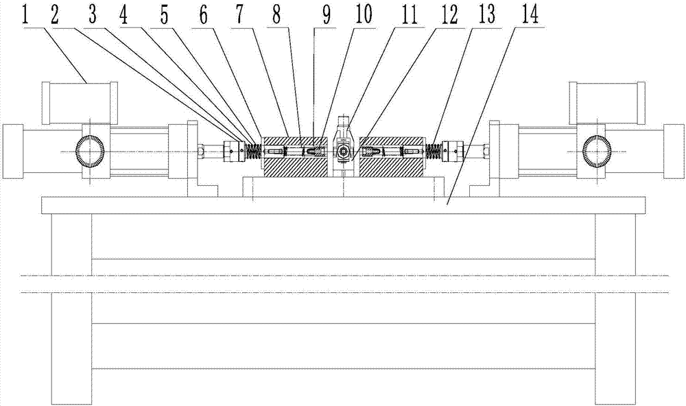
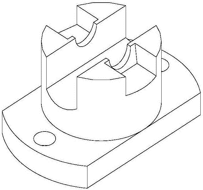
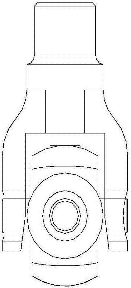
[0013] Such as figure 1 As shown, a ten-byte riveting machine includes a knife cylinder 1, an adjusting nut 2, a lock nut 3, a push rod 4, a spring 5, a fixing block 7, a connecting rod 8, a positioning sleeve 9, a riveting head 10, Joint fork workpiece 11, positioning block 12, telescopic spring 13, base plate 14, the left and right sides of the upper end of base plate 14 are respectively provided with a knife cylinder 1, and the middle part between two knife cylinders 1 is provided with a positioning block 12, and the positioning block 12 The left and right sides are respectively provided with fixed blocks 7, and the fixed block 7 on the left is respectively provided with a connecting rod 8, a positioning sleeve 9, and a riveting joint 10, and a spring 5 is arranged on the left side of the connecting rod 8, and the spring 5 is set on the push rod 4 ,...


PUM


Abstract

The invention provides a riveting machine and method for cross joints, belongs to the field of universal joint assembly, and particularly relates to the technical field of riveting machines for the cross joints. Unclamping cylinders are arranged on the left side and the right side of the upper end of a bottom plate correspondingly. A positioning block is arranged on the middle portion between the two unclamping cylinders. Fixing blocks are arranged on the left side and the right side of the positioning block correspondingly. A connection rod, a positioning sleeve and a rivet joint are arranged on the fixing block located on the left side, wherein a spring is arranged on the left side of each connection rod and is arranged on one push rod in a sleeving manner, a regulation nut and a locking nut are arranged on the left side of the push rod, and a telescopic spring is arranged on the portion, on the right side of the fixing block on the right side, of the other push rod. A yoke workpiece is clamped on the positioning block. By means of the riveting machine and method, the aims of achieving uniform riveting depths and matching of the cross joints and needle bearing clearance and greatly improving the production efficiency are achieved.

Description

technical field [0001] The invention belongs to the field of universal joint assembly, and specifically relates to the technical field of a ten-byte riveting machine. Background technique [0002] At present, when the universal joint transmission is realized by assembling needle roller bearings at both ends of the ten-byte and ten-byte, in order to prevent the axial movement of the ten-byte and the needle roller bearing after the assembly is completed, the bearing will be disengaged, which will cause the universal joint to be scrapped. , it is necessary to use the method of riveting to axially limit the needle bearing. In order to solve this problem, the riveting head is mainly used for riveting directly. Since the fork workpiece with the ten-point and needle roller bearing is forged, the wall of the fork workpiece is thin, and the opening of the fork workpiece is produced under the high-pressure riveting force. Deformation, resulting in uneven depth of the upper and lower ...

Claims


Application Information

Patent Timeline
Patent Type & Authority Applications(China)
IPC IPC(8): B21D39/00B21D43/00
CPCB21D39/00B21D43/003
Inventor 姜玉红朱伟刘建伟
Owner JIANGSU CCVI BEARING
Learn More