Mounting structure of detergent dispenser

A detergent injection and installation structure technology, applied in the field of washing machines, can solve the problems of uneven force on the water storage box, messy feeling of the user as a whole, and safety, and achieve the effects of good intuitive feeling, reduced quantity, and reduced possibility of fire

Active Publication Date: 2017-07-07
QINGDAO HAIER WASHING ELECTRIC APPLIANCES CO LTD
View PDF3 Cites 3 Cited by
  • Summary
  • Abstract
  • Description
  • Claims
  • Application Information

AI Technical Summary

Problems solved by technology

[0003] Most of the existing detergent dispensers are installed above the inside of the washing machine cabinet, at the corners of the side panels and the top panel. The side of the water box is connected to the side plate of the box body, the rear end of the water storage box and the other side are suspended in the air without any connection structure, resulting in a large force on the front end of the water storage box and one side connected to it, and Uneven stress on the entire water storage box
[0004] Most of the water storage box and the front panel of the cabinet or the control panel are connected by screws, at least two places, when the drawer assembly that can be pushed and pulled is matched with the front panel of the cabinet or the control panel, a positioning structure is required, at least two places, when the user pulls the drawer assembly, Many screws and positioning structures are exposed in front of the user, and the overall feeling of the user will be very messy
[0005] Generally, the water injection pipes are connected to the rear of the washing machine, and are connected to the water storage box through a hose. A solenoid valve for controlling the on-off of the pipeline needs to be installed between them. The hoses are mostly rubber hoses, and there are too many around the solenoid valve. The rubber hose will pose a safety hazard

Method used


Image

  • Mounting structure of detergent dispenser
  • Mounting structure of detergent dispenser
  • Mounting structure of detergent dispenser

Examples


Embodiment Construction

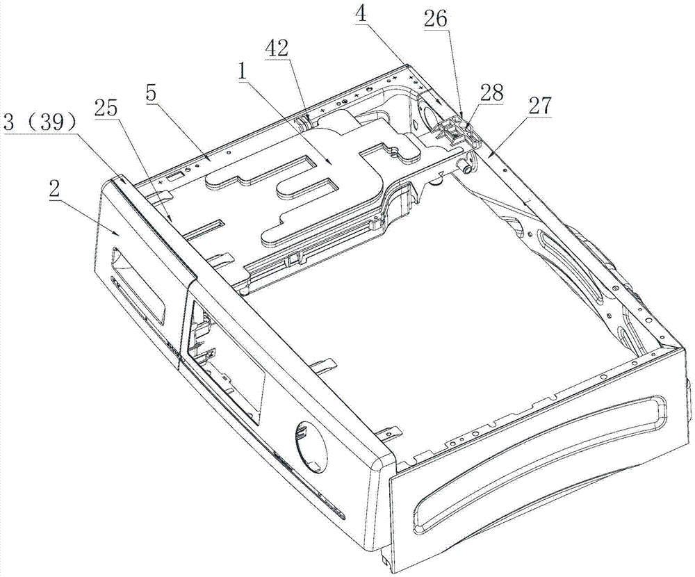
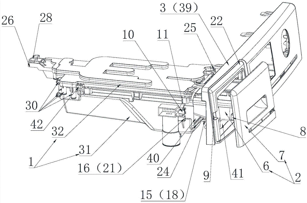
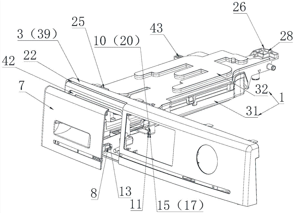
[0029] The installation structure of a detergent dispenser according to the present invention comprises: a water storage box 1, a drawer assembly 2 that can be pushed in and out of the water storage box, and the water storage box 1 is installed in the upper part of the box and the box. The body front plate 3 is matched, and the inlet and outlet 44 of the drawer assembly 2 are provided at the matching position. The water storage box 1 is provided with a first opening 40 corresponding to the box body front plate 3, and the box body front plate 3 is provided with a second The opening 41, the first opening 40 and the second opening 41 form an inlet and outlet 44 of the drawer assembly 2 through the inlet and outlet 44, the drawer assembly 2 enters and exits the water storage box 1 through the inlet and outlet 44, and pulls out the water storage box 1 and then faces the drawer assembly 2 add detergent, push the rear drawer assembly 2 of the water storage box 1 to cooperate with the f...


PUM


Abstract

The invention relates to a mounting structure of a detergent dispenser. The dispenser comprises a water storage box and a drawer assembly that can pull in and out of the water storage box. The water storage box is installed at the upper part of a box body and in the structure of a long strip. The front end of the water storage box is connected with the front end of the box body. The back end of the water storage box is connected with the back end of the box body. The back end of the water storage box extends to a back board of the box body and overlap joint with the back board of the box body. The connection is reliable. Meanwhile, the extending part is integrally provided with a water inlet path and a water inlet. A water inlet pipeline of a washing machine is directly connected to the water inlet through an electromagnetic valve. Water flows into function regions of the drawer assembly through the water inlet and the water inlet path and flows through a water outlet of the water storage tank of the water storage box. The overuse of multiple rubber hoses is avoided so to as avoid possibility of fire disasters.

Description

Technical field [0001] The invention relates to the field of washing machines, in particular to an installation structure of a detergent dispenser. Background technique [0002] In the existing drum washing machine, the detergent dispenser includes a water storage box connected with a water injection pipe. The water storage box has a drawer assembly that can be pushed and pulled. The drawer assembly is provided with multiple compartments, including a detergent box for storing detergent. Softener box for storing liquid softener, etc. During washing, water flows down from the top of the dispenser to dissolve detergent or softener, and enter the washing tub together with water. [0003] Most of the existing detergent dispensers are installed above the inside of the washing machine cabinet, at the corners of the side panels and the top panel. Most of the existing installations generally involve connecting the front end of the water storage box with the front panel of the cabinet or th...

Claims


Application Information

Patent Timeline
Patent Type & Authority Applications(China)
IPC IPC(8): D06F39/02
CPCD06F39/02D06F39/022
Inventor 黄涛王艳丽张华成
Owner QINGDAO HAIER WASHING ELECTRIC APPLIANCES CO LTD
Why Eureka
Try Eureka