Improved LED illumination lamp device

An LED lighting lamp, an improved technology, applied in lighting devices, fixed lighting devices, lighting auxiliary devices, etc., can solve the problems of LED lights such as heavy workload, inconvenient installation or disassembly, poor practical performance, etc., to meet lighting needs , Easy installation and maintenance, simple structure

Inactive Publication Date: 2017-07-07
顾彩晓
View PDF3 Cites 8 Cited by
  • Summary
  • Abstract
  • Description
  • Claims
  • Application Information

AI Technical Summary

Problems solved by technology

[0002] LED lamps have gradually replaced the existing incandescent lamps and fluorescent lamps as a new generation of lighting equipment for daily life. Because some specific occasions require the installation position of the LED to be at a certain angle from the ground, it is required that the irradiation angle of the installed LED lamps be adjustable so that To adapt to the installation occasion, the existing LED angle adjustments are all manually adjusted, so that the LED lamp has a large workload during installation, poor practical performance, and poor use effect; at the same time, the existing lighting lamps are fixed by screws, which is not easy to install or use. Disassembly, especially in some special places, due to the small and narrow installation surface, the traditional fixing method such as screw fixing has caused great obstacles to the installation, and it is quite inconvenient to use

Method used


Image

  • Improved LED illumination lamp device
  • Improved LED illumination lamp device
  • Improved LED illumination lamp device

Examples


Embodiment Construction

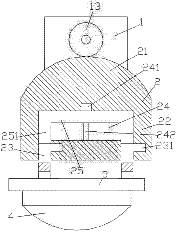
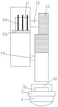
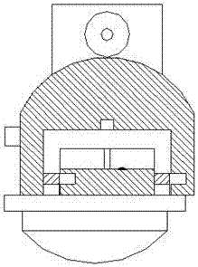
[0019] Such as Figure 1-Figure 5 As shown, an improved LED lighting device of the present invention includes a mounting plate 1, a lamp holder 2 that is rotatably connected to the mounting plate 1, and a lighting assembly 3 that is mated and connected to the lamp holder 2. The front end of the mounting plate 1 An angle adjustment motor 11 is embedded above the surface, and a rotating pin shaft 14 is provided below the front end of the mounting plate 1. The angle adjustment motor 11 is rotatably connected with a rotating shaft 12, and the rotating shaft 12 is fixedly provided with a drive gear. 13. The rotating pin shaft 14 is connected to the lamp holder 2 in a rotational fit. The lamp holder 2 includes a circular arc portion 21 and a mounting portion 22. External teeth are provided on the outer side of the circular arc portion 21. The circular arc Part 21 is meshed with the drive gear 13 through the external teeth, and through chute 23 is symmetrically arranged in the connec...


PUM


Abstract

The invention discloses an improved LED illumination lamp device. The improved LED illumination lamp device comprises a mounting plate, a lamp holder rotationally connected with the mounting plate in a cooperating manner, and an illumination lamp assembly connected with the lamp holder in a cooperating manner. An angle adjusting motor is embedded in the upper portion of the front end face of the mounting plate. A rotary pin shaft is arranged on the lower portion of the front end face of the mounting plate. A rotary shaft is rotationally connected to the angle adjusting motor. A drive gear is fixedly arranged on the rotary shaft. The rotary pin shaft is rotationally connected with the lamp holder in a cooperating manner. The lamp holder comprises an arc part and a mounting connecting part. External connecting teeth are arranged on the outer side of the arc part, and the arc part is in engagement connection with the drive gear through the external connecting teeth. Through sliding grooves are formed in the mounting connecting part in a bilateral symmetry manner. A guide sliding groove is formed in the position, between the through sliding grooves, in the mounting connecting part. The inner side of the upper portion of each through sliding groove communicates with the guide sliding groove. A locking groove communicating with the corresponding through sliding groove is formed in the position, on the right side of the lower portion of each through sliding groove, in the mounting connecting part. A guide sliding plate connected in a sliding fit manner is arranged in the guide sliding groove, and the two sides of the guide sliding plate are provided with locking sliding blocks stretching into the through sliding grooves. The improved LED illumination lamp device is simple in structure and convenient to mount, and angle adjustment is achieved.

Description

technical field [0001] The invention relates to the technical field of lighting lamps, in particular to an improved LED lighting lamp device. Background technique [0002] LED lamps have gradually replaced the existing incandescent lamps and fluorescent lamps as a new generation of lighting equipment for daily life. Because some specific occasions require the installation position of the LED to be at a certain angle from the ground, it is required that the irradiation angle of the installed LED lamps be adjustable so that To adapt to the installation occasion, the existing LED angle adjustments are all manually adjusted, so that the LED lamp has a large workload during installation, poor practical performance, and poor use effect; at the same time, the existing lighting lamps are fixed by screws, which is not easy to install or use. Disassembly, especially in some special places, due to the small and narrow installation surface, traditional fixing methods such as screw fixin...

Claims


Application Information

Patent Timeline
Patent Type & Authority Applications(China)
IPC IPC(8): F21S8/00F21V21/14F21V29/74F21Y115/10
CPCF21S8/00F21V21/14F21V29/74
Inventor 顾彩晓
Owner 顾彩晓
Why Eureka
Try Eureka