Rotary type variable resistor

A resistor and rotary technology, applied in the direction of adjustable resistors, resistors, sliding contact resistors, etc., can solve problems such as difficult production, increased cost, and limited rotation angle

Active Publication Date: 2017-07-07
TAIWAN ALPHA ELECTRONICS
View PDF8 Cites 4 Cited by
  • Summary
  • Abstract
  • Description
  • Claims
  • Application Information

AI Technical Summary

Problems solved by technology

[0003] Based on the above, common variable resistors can be roughly divided into reciprocating sliding variable resistors and rotary variable resistors according to their structures, and the structure of rotary variable resistors can also be divided into single-turn resistors and multi-turn resistors. The structure of the coil resistance, the variable resistor of the single-turn resistance type is mainly provided with contacts at both ends of the C-type resistance of a circle, so it can move back and forth between the two ends to generate a voltage division signal, while the multi-turn resistance Variable resistors mainly use multi-turn C-type resistors to generate multiple voltage division signals; however, although multi-turn resistance variable resistors can output more voltage division signals, due to the structure of multi-turn resistance Increase the complexity of the manufacturing process, making it difficult to produce, so it will increase the cost relatively
Regardless of whether it is a single-turn resistance type or a multi-turn resistance type rotary variable resistor, the rotation angle will be limited due to the structure of the C-type electric group.

Method used


Image

  • Rotary type variable resistor
  • Rotary type variable resistor
  • Rotary type variable resistor

Examples


Embodiment Construction

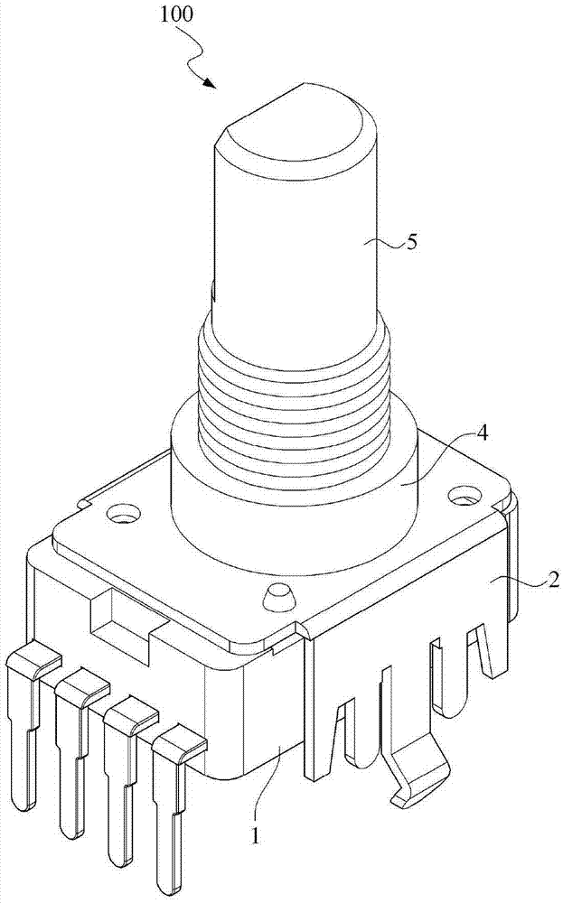
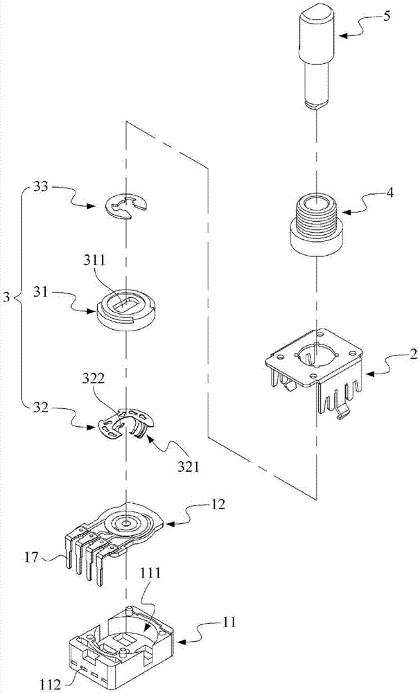
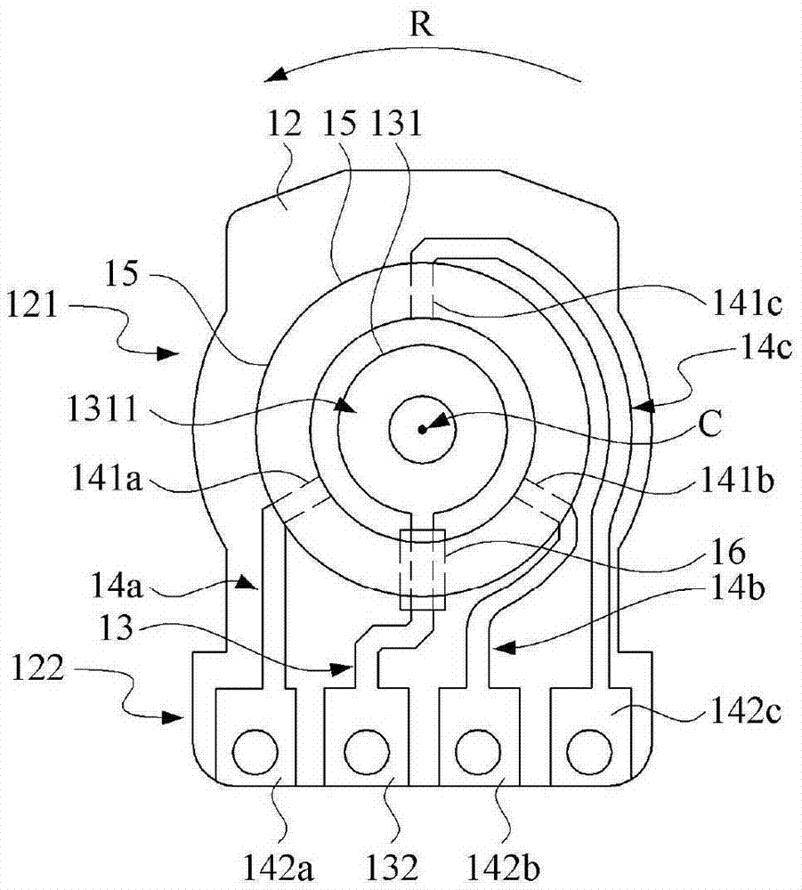
[0048] see Figure 1 to Figure 4 , figure 1 A three-dimensional schematic diagram showing a rotary variable resistor provided by a preferred embodiment of the present invention; figure 2 A three-dimensional exploded schematic diagram showing a rotary variable resistor provided by a preferred embodiment of the present invention; image 3 A schematic plan view showing a resistive circuit module provided by a preferred embodiment of the present invention; Figure 4 A schematic circuit diagram of a resistance circuit module provided by a preferred embodiment of the present invention is shown.

[0049] Such as Figure 1 to Figure 4 As shown, a rotary variable resistor 100 includes a resistor circuit module 1 , a fixing frame 2 , a brush assembly 3 , a bushing 4 and a shaft 5 .

[0050] The resistance circuit module 1 comprises an insulating base 11, a circuit substrate 12, an output circuit 13, three input circuits 14a, 14b, 14c, a ring-type resistance layer 15, an insulating ...


PUM


Abstract

The invention provides a rotary type variable resistor. The rotary type variable resistor comprises a resistor circuit module, a fixed frame, an electric brush assembly and a rotary shaft, wherein the resistor circuit module comprises a circuit substrate, an output circuit, three input circuits and an annular type resistor layer; the output circuit has an annular electric brush contact region; each of the three input circuits comprises a resistor contact end and an input terminal connecting end separately; any two of the three resistor contact ends are connected with the central axis of the annular electric brush contact region to form an included angle of 120 degrees; the annular resistor layer and the electric brush contact ends are coaxially arranged at intervals, and are in contact with the three resistor contact ends respectively; the fixed frame is fixedly arranged on the resistor circuit module; the electric brush assembly rotationally bridges the annular electric brush contact region and the annular resistor layer; and the rotary shaft is hinged to the electric brush assembly. According to the rotary type variable resistor, two corresponding voltage division signals can be generated at any angles, so that a user can accurately judge the position of an electric brush according to the two corresponding voltage division signals based on a corresponding judging rule.

Description

technical field [0001] The invention relates to a rotary variable resistor, in particular to a rotary variable resistor which utilizes three input circuits and a ring-shaped resistance layer. Background technique [0002] Generally speaking, electronic devices controlled by variable resistors can be seen everywhere in daily life, such as in audio equipment to control the volume; among them, the main principle of variable resistors is to set a voltage between two fixed contacts. Resistor, and for the user to move the sliding contact back and forth on the resistor to generate a change in the divided voltage between the two fixed contacts, and then generate a corresponding divided voltage signal. [0003] Based on the above, common variable resistors can be roughly divided into reciprocating sliding variable resistors and rotary variable resistors according to their structures, and the structure of rotary variable resistors can also be divided into single-turn resistors and mul...

Claims


Application Information

Patent Timeline
IPC IPC(8): H01C10/00H01C10/30H01C10/32
CPCH01C10/00H01C10/30H01C10/32
Inventor 黄子轩刘韦良何建志
Owner TAIWAN ALPHA ELECTRONICS
Why Eureka
Try Eureka