
Implementation method for integrating scanning function in passbook printing machine

A passbook printer and the technology of the implementation method, which are applied in the field of integrated scanning functions, can solve the problems of high hardware, prolonged scanning time, and slow scanning speed, and achieve the effects of precise position and size, wide application prospects, and reduced hardware costs

Pending Publication Date: 2019-10-18
FUJIAN SHIDA COMP EQUIP
View PDF0 Cites 0 Cited by
  • Summary
  • Abstract
  • Description
  • Claims
  • Application Information

AI Technical Summary

Problems solved by technology

At present, most of the passbook printers used for passbook printing on the market use the built-in scanning function, and this kind of built-in scanning function makes the assembly of the passbook printer more complicated. During the scanning process, the image data of the entire width of the scanning tube is collected. And after the image data of the entire printing medium is collected, the image correction processing and uploading are performed. When scanning a printing medium with a small size, this will forcibly increase the hardware overhead of the printer control system and prolong the scanning time. The hardware is successfully raised, but the scanning speed is slow
The passbook printer with this structure cannot fully meet the needs of use

Method used


Image

  • Implementation method for integrating scanning function in passbook printing machine
  • Implementation method for integrating scanning function in passbook printing machine
  • Implementation method for integrating scanning function in passbook printing machine

Examples


Embodiment Construction

[0026] In order to make the above-mentioned features and advantages of the present invention more comprehensible, the following specific embodiments are described in detail with reference to the accompanying drawings, but the present invention is not limited thereto.

[0027] refer to Figure 1 to Figure 5

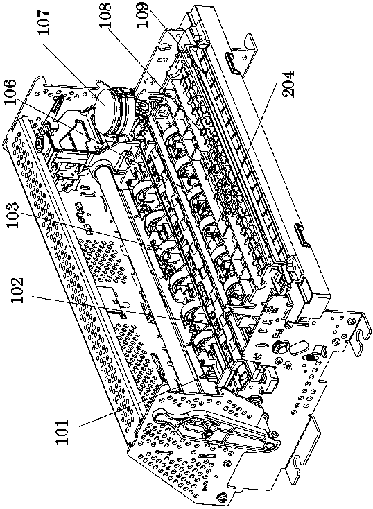
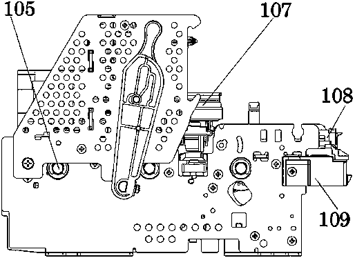
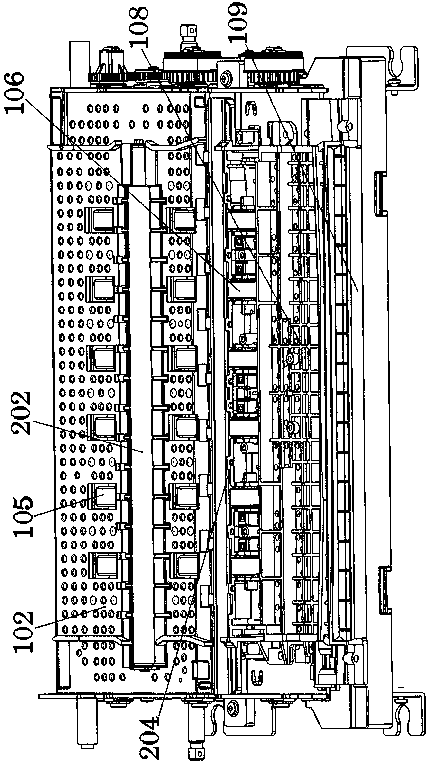
[0028] A method for realizing an integrated scanning function in a passbook printer, comprising a contact scanning paper-feeding mechanism, the contact-type scanning paper-feeding mechanism comprising a rear upper paper guide frame 101 and a rear lower paper guide located at the lower side of the rear upper paper guide frame The frame 102 is located at the front side of the upper rear paper guide frame and the lower rear paper guide frame, and is respectively provided with a front upper paper guide plate 108 and a front lower paper guide plate 109, and a first rear paper guide plate is embedded in the rear upper paper guide frame from front to rear. The upper paper feed w...


PUM


Abstract

The invention relates to an implementation method for integrating a scanning function in a passbook printing machine, wherein a contact scanning paper feeding mechanism comprises a back upper paper guide frame, a back lower paper guide frame, a front upper paper guide plate and a front lower paper guide plate; a first back upper paper feeding wheel, a first scanning pipe and a second back upper paper feeding wheel are embedded in the back upper paper guide frame from front to back; a back lower paper feeding wheel and a second scanning pipe are embedded in the back lower paper guide frame fromfront to back; the first back upper paper feeding wheel is positioned on the upper side of the back lower paper feeding wheel; the first scanning pipe and the second scanning pipe are placed in a mirror image way; a printing head capable of moving left and right is arranged on the front side of the back upper paper guide frame and the back lower paper guide frame; a reflecting type photoelectricsensor is arranged on the printing head; a front paper feeding wheel and four pairs of bijection type photoelectric sensors are embedded in the front upper paper guide plate; the front upper paper guide plate and the front lower paper guide plate are arranged on the front side of the printing head; and a control system controls the contact scanning paper feeding mechanism and a hardware assembly through a motor to integrate the scanning function in the passbook printing machine. The method is simple in process, low in hardware cost, high in scanning speed and reliable in effect.

Description

technical field [0001] The invention relates to a method for realizing the integrated scanning function in a passbook printer, which is suitable for the field of passbook printers. Background technique [0002] Passbook, commonly known as red book, is a book used to record bank transactions in deposit accounts. Its size varies from country to country and from banking institution to country, and can be the size of a checkbook, or the size of a passport. At present, most of the passbook printers used for passbook printing on the market use the built-in scanning function, and this kind of built-in scanning function makes the assembly of the passbook printer more complicated. During the scanning process, the image data of the entire width of the scanning tube is collected. And after the image data of the entire printing medium is collected, the image correction processing and uploading are performed. When scanning a printing medium with a small size, this will forcibly increase...

Claims


Application Information

Patent Timeline
Patent Type & Authority Applications(China)
IPC IPC(8): B41J3/44B41J11/00
CPCB41J3/445B41J11/0095
Inventor 林艳青蒋旭峰曾晋
Owner FUJIAN SHIDA COMP EQUIP
Learn More