Equipment binding system

A technology of equipment and terminal equipment, applied in branch equipment, telephone communication, instruments, etc., can solve problems such as time-consuming and labor-intensive

Inactive Publication Date: 2017-07-07
OPPLE LIGHTING
View PDF5 Cites 6 Cited by
  • Summary
  • Abstract
  • Description
  • Claims
  • Application Information

AI Technical Summary

Problems solved by technology

If there are too many lamps, especially commercial lighting with hundreds of nodes, it will t

Method used


Image

  • Equipment binding system
  • Equipment binding system
  • Equipment binding system

Examples


Embodiment Construction

[0050] Hereinafter, exemplary embodiments of the present disclosure will be described in more detail with reference to the accompanying drawings. Although exemplary embodiments of the present disclosure are shown in the drawings, it should be understood that the present disclosure can be implemented in various forms and should not be limited by the embodiments set forth herein. On the contrary, these embodiments are provided to enable a more thorough understanding of the present disclosure and to fully convey the scope of the present disclosure to those skilled in the art.

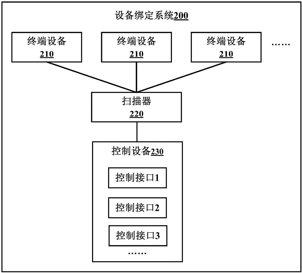
[0051] In order to solve the above technical problem, an embodiment of the present invention provides a device binding system. figure 2 It shows a schematic structural diagram of a device binding system according to an embodiment of the present invention. Such as figure 2 As shown, the device binding system 200 may include: multiple terminal devices 210, a scanner 220, and a control device 230.

[0052] In t...


PUM


Abstract

The invention provides an equipment binding system, which comprises a plurality of terminal devices, a scanner and control equipment, wherein a graph identifier used for expressing the related information of the device is arranged on each terminal device; the scanner is used for scanning and identifying the graph identifier on each terminal device to obtain related information of each terminal device; the control equipment is connected to the scanner and is used for obtaining an identification of a new control interface on a display interface when the related information of any terminal device is obtained from the scanner, and establishing a corresponding relation between the identification of the control interface and the related information of any terminal device to realize binding of the control interface and any terminal device in order to carry out remote control on the terminal device bound with the triggered control interface when any control interface is triggered. According to the embodiment of the invention, the binding of each control interface on the control equipment and each terminal device can be flexibly realized, and a binding process is orderly and efficient.

Description

Technical field [0001] The invention relates to the technical field of intelligent control, in particular to a device binding system. Background technique [0002] In daily life, people will come into contact with many terminal devices, such as lighting fixtures, televisions, air conditioners, cameras, etc. These terminal devices bring people entertainment and convenience in life. In practical applications, these terminal devices can be bound to a control device (such as a smart phone, a tablet computer, or a personal computer, etc.), and the control device can then remotely control the terminal device. However, there are some problems in the process of device binding. [0003] Take lighting lamps as an example. With the rapid development of wireless communication technology, many lamps and lanterns products with wireless communication functions are coming. However, the physical equipment (lamp body) and logical equipment (that is, virtual lamps created on the control device) of w...

Claims


Application Information

Patent Timeline
IPC IPC(8): H04L12/28H04M1/725G06F17/30
CPCG06F16/9554H04L12/2803H04L12/2807H04M1/72406H04M1/72409H04M1/72415
Inventor 邹晓亮罗顺
Owner OPPLE LIGHTING
Why Eureka
Try Eureka