Automatic crimping structure of FOG liquid crystal screen
A screen and liquid crystal technology, which is applied in the field of FOG liquid crystal screen automatic crimping structure, can solve the problems of high stability requirements, low efficiency, and low success rate of point screen, achieve high precision, accurate positioning, improve test efficiency and point The effect of screen success rate
- Summary
- Abstract
- Description
- Claims
- Application Information
AI Technical Summary
Problems solved by technology
Method used
Image

Examples
Embodiment approach 1
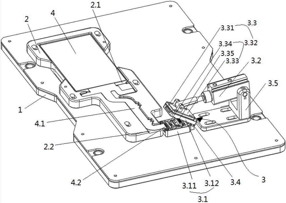
[0024] Embodiment 1, such as figure 1 As shown, the rotating shaft 3.4 is arranged at the ends of the clamping fixed part 3.11 and the clamping movable part 3.12; the driving part 3.2 is fixed on the surface of the carrier 2 through the frame 3.5, and the driving part The output end of 3.2 is rotatably connected to the upper surface of the clamping movable part 3.12, and the fixed end of the driving part 3.2 is rotatably connected to the frame 3.5; the connection between the output end of the driving part 3.2 and the clamping movable part 3.12 and the rotating shaft 3.4 are located at opposite ends of the clamping movable part 3.12.
[0025] The signal line 3.32 includes an upper PCB 3.33 connected to the signal transfer probe 3.31, a lower PCB 3.34 electrically connected to the control terminal, and a signal transmission probe 3.35 connected to the upper PCB 3.33 and the lower PCB 3.34. Preferably, the upper PCB 3.33 is located on the surface of the clamping movable part 3.1...
Embodiment approach 2
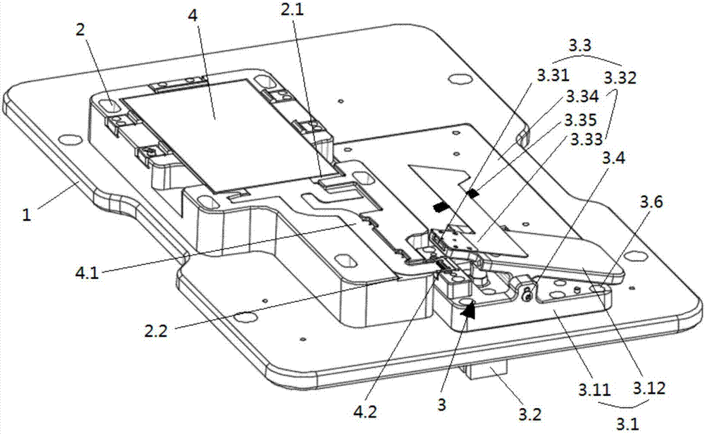
[0027] Embodiment 2, such as figure 2 As shown, the rotating shaft 3.4 is arranged in the middle of the clamping fixed part 3.11 and the clamping movable part 3.12; the driving part 3.2 is arranged under the carrier 2, and the output end of the driving part 3.2 can be Pass through the carrier 2 and the clamping fixed part 3.11 to abut against the bottom surface of the clamping movable part 3.12; there is also a compression spring 3.6 between the clamping fixed part 3.11 and the clamping movable part 3.12; The crimping spring 3.6 and the driving part 3.2 are located on both sides of the rotating shaft 3.4, and the output end of the driving part 3.2 is located between the rotating shaft 3.4 and the signal transfer probe 3.31.
[0028]The signal line 3.32 includes an upper PCB 3.33 connected to the signal transfer probe 3.31, a lower PCB 3.34 electrically connected to the control terminal, and a signal transmission probe 3.35 connected to the upper PCB 3.33 and the lower PCB 3.3...
PUM
 Abstract
Description
Claims
Application Information
 - Generate Ideas
- Intellectual Property
- Life Sciences
- Materials
- Tech Scout
- Unparalleled Data Quality
- Higher Quality Content
- 60% Fewer Hallucinations
Browse by: Latest US Patents, China's latest patents, Technical Efficacy Thesaurus, Application Domain, Technology Topic, Popular Technical Reports.
© 2025 PatSnap. All rights reserved.Legal|Privacy policy|Modern Slavery Act Transparency Statement|Sitemap|About US| Contact US: help@patsnap.com