A new energy vehicle charging device

A technology for new energy vehicles and charging devices, applied in electric vehicle charging technology, charging stations, coupling devices, etc., can solve the problems of easy loosening, decreased life of charging cables, and easily damaged charging plugs, so as to reduce the occurrence of electric shock accidents and prevent The effect of unexpected termination of charging and improved connection stability

Active Publication Date: 2018-06-12
JIANGSU XIYI HIGH NEW DISTRICT TECH DEV CO LTD
View PDF4 Cites 4 Cited by
  • Summary
  • Abstract
  • Description
  • Claims
  • Application Information

AI Technical Summary

Problems solved by technology

[0002] With the emergence of electric vehicles, the use of charging piles for electric vehicles has increased. When users use the existing electric vehicle charging piles to charge electric vehicles, they plug the charging plug directly into the socket for charging. If it is loose, there will be poor contact, and because there is a large current flowing through the socket, the charging plug is easily damaged. When the charging pile is charging the electric vehicle, pulling out the charging gun will cause a safety accident, causing casualties, If the device is damaged or even causes a fire, in order to avoid safety accidents, it is necessary to lock the charging gun during the charging process and unlock it after charging; if the power is cut off during the charging process, the charging gun cannot be pulled out, and manual unlocking requires charging Pile maintenance personnel operate, which brings inconvenience to the actual application. In addition, the existing charging pile automatic charging line, the user often does not place the charging line as required after use, but throws the charging line on the ground at will; in this way, the charging line is easy to use. Various unexpected stresses, such as trampling by people, rolling over by cars, etc., will cause damage to the outer insulation of the charging line, resulting in a decrease in the life of the charging line, resulting in electric shock accidents

Method used


Image

  • A new energy vehicle charging device
  • A new energy vehicle charging device
  • A new energy vehicle charging device

Examples


Embodiment Construction

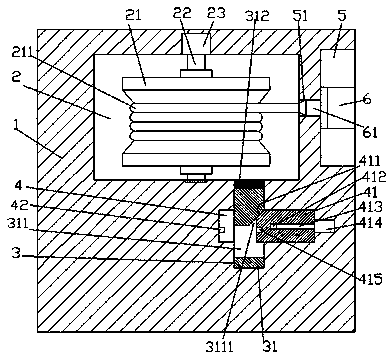
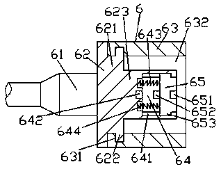
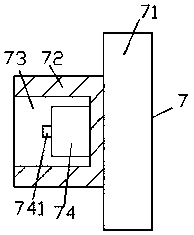
[0025] Such as Figure 1-Figure 9 As shown, a new energy vehicle charging device of the present invention includes a charging pile 1 and a car interface 7, the charging pile 1 is provided with a wire receiving chamber 2, and the charging pile 1 on the right side of the wire receiving chamber 2 An operation slot 5 is provided in the outer end surface, and a through hole 51 is provided between the operation slot 5 and the wire receiving chamber 2, and the top and the wire receiving chamber are arranged longitudinally on the inner bottom wall on the right side of the wire receiving chamber 2. 2 connected with the first chute 3, the middle position of the first chute 3 is transversely provided with a second chute 4 and communicated with the first chute 3, and the longitudinal chamber 2 is set There is a rotating shaft 22, and the top of the rotating shaft 22 is dynamically connected with the take-up motor 23. The rotating shaft 22 is fixed with a take-up reel 21 in the circumferen...


PUM


Abstract

The invention discloses a novel new energy automobile charging interface and a charging device. The charging device comprises a charging pile and the automobile interface. A take-up cavity is formed in the charging pile. An operating groove is formed in the outer end face, on the right side of the take-up cavity, of the charging pile. A through hole is formed between the operating groove and the take-up cavity. A first sliding groove with the top communicating with the take-up cavity is longitudinally formed in the inner bottom wall of the right side of the take-up cavity. A second sliding groove is transversely formed in the middle of the first sliding groove in a penetrating mode and communicates with the first sliding groove. A rotating shaft is longitudinally arranged in the take-up cavity. The top of the rotating shaft is connected with a take-up motor in a power fit mode. A take-up reel is fixedly and circumferentially arranged on the rotating shaft. A charging line is wound on the take-up reel. A door locking part is arranged on the right side face of the operating groove. A charging gun is arranged in the operating groove. A plug used for being in plugging fit with the through hole is arranged on the left side end face of the charging gun. The left side end face of the plug is fixedly connected with the charging line. A connecting block is arranged in the charging gun. A protruding block is arranged on the right side end face of the connecting block. The charging device is simple in structure, convenient to operate, stable in connection and high in safety.

Description

technical field [0001] The invention relates to the technical field of new energy vehicle charging, in particular to a new energy vehicle charging device. Background technique [0002] With the emergence of electric vehicles, the use of charging piles for electric vehicles has increased. When users use the existing electric vehicle charging piles to charge electric vehicles, they plug the charging plug directly into the socket for charging. If it is loose, there will be poor contact, and because there is a large current flowing through the socket, the charging plug is easily damaged. When the charging pile is charging the electric vehicle, pulling out the charging gun will cause a safety accident, causing casualties, If the device is damaged or even causes a fire, in order to avoid safety accidents, it is necessary to lock the charging gun during the charging process and unlock it after charging; if the power is cut off during the charging process, the charging gun cannot be...

Claims


Application Information

Patent Timeline
Patent Type & Authority Patents(China)
IPC IPC(8): B60L11/18H01R13/72H01R13/629H01R13/639H01R13/642
CPCB60L53/16H01R13/629H01R13/639H01R13/642H01R13/72Y02T10/70Y02T10/7072Y02T90/14
Inventor 郭涛
Owner JIANGSU XIYI HIGH NEW DISTRICT TECH DEV CO LTD
Why Eureka
Try Eureka