Water rescue equipment and method

A kind of equipment and technology in the horizontal direction, which can be used in sea and air rescue equipment, life rafts, life buoys and other directions, which can solve the problems of low survival rate and achieve the effect of strong mobility.

Inactive Publication Date: 2017-07-14
袁洪翊
View PDF3 Cites 10 Cited by
  • Summary
  • Abstract
  • Description
  • Claims
  • Application Information

AI Technical Summary

Problems solved by technology

The above-mentioned various reasons lead to a low survival rate after the drowning person is rescued

Method used


Image

  • Water rescue equipment and method
  • Water rescue equipment and method
  • Water rescue equipment and method

Examples


Embodiment 1

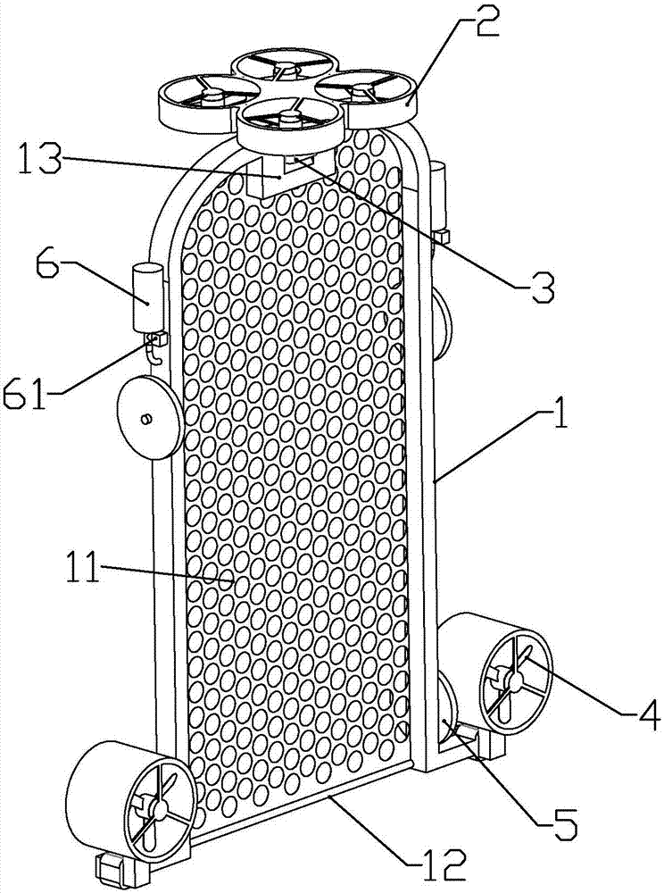
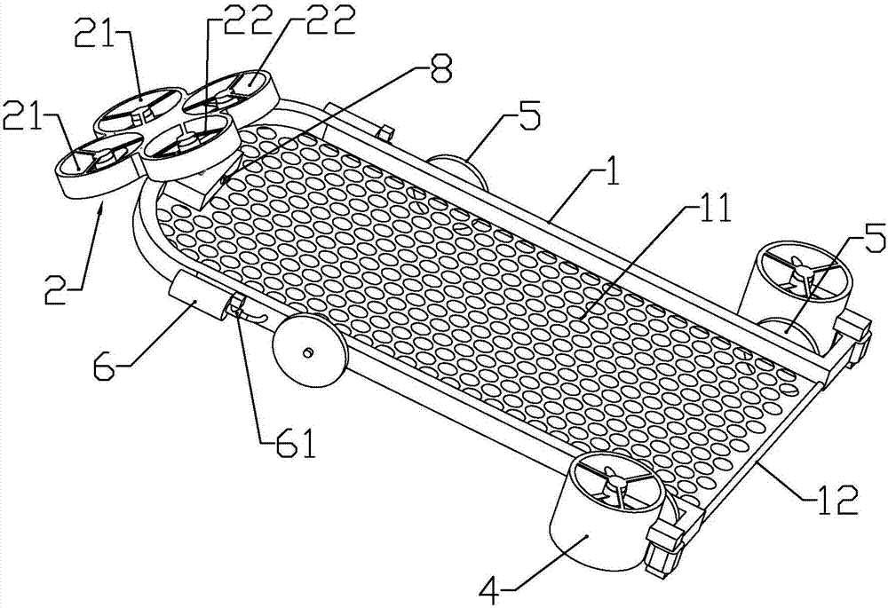
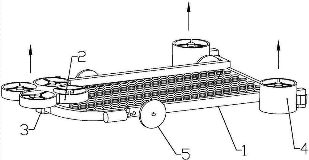
[0045] according to Figure 1 to Figure 3 As shown, the present embodiment is a kind of water rescue equipment, including a quadrocopter 2, a stepper motor 3 fixedly connected to the lower end of the quadcopter and the output shaft is horizontally arranged, and a U motor 3 fixedly connected to the output shaft of the motor. Type bracket 1, the nylon net 11 that is connected on the U-type bracket, and the rear driving water wheel 4 that is respectively fixedly connected on the outside of the two ends of the U-type bracket with the pushing direction perpendicular to the U-type bracket; the four-axis A camera 8 is installed at the lower end of the aircraft or in the middle of the U-shaped bracket.

[0046] The U-shaped bracket is rotatably connected with rollers 5 at least at positions close to both ends.

[0047] A controller is installed in the quadrocopter, and the driving motors of four fans, the driving motors of the two rear driving water wheels, the stepping motor and the...

Embodiment 2

[0066] combine Figure 4 to Figure 6 As shown, this embodiment makes the following improvements on the basis of Embodiment 1: the lower ends of both sides of the U-shaped bracket are formed with an airbag container 14 along the length direction, and an airbag container is installed in the airbag container to protrude to the airbag container after inflation. The strip-shaped airbag 7 at the lower end is formed with clamping projections 15 in order to limit the uninflated airbag in the airbag groove along the length direction of the airbag groove on both side walls of the airbag groove; The two sides of the U-shaped bracket are also equipped with a gas storage bottle 6 for inflating the air bag. The outlet end of the gas storage bottle is connected with a solenoid valve 61, and the gas outlet of the solenoid valve is connected with the air bag through a pipeline; Electrically connected with the controller.

[0067] The upper ends of both sides of the U-shaped bracket are equipp...

Embodiment 3

[0072] combine Figure 7 As shown, the present embodiment makes the following improvements on the basis of embodiment 1 or 2: the support rod 12 is removed, and two rollers 18 are rotatably installed between the two sides of the U-shaped bracket near the front and rear ends. , the nylon mesh cover forms a conveying mesh belt between two rollers, and one end of a roller on the U-shaped support is equipped with a motor 17 for driving the roller and the nylon mesh to rotate.

[0073] The two ends of the nylon mesh close to both sides of the U-shaped bracket are fixedly connected with a cylindrical cross-section with elastic positioning rings, and the inner walls on both sides of the U-shaped bracket are equipped with C-shaped snap rings that are slidably connected with the positioning rings ( not shown in the figure).

[0074] In order to further shorten the rescue time, the nylon net is installed between two rollers and driven by a motor to rotate. After part of the body of the...


PUM


Abstract

The invention discloses water rescue equipment. The water rescue equipment comprises a quadcopter, a stepping motor fixedly connected with the lower end of the quadcopter and with an output shaft horizontally arranged, a U-type support fixedly connected with the output shaft of the motor, a nylon net connected to the U-type support, and rear drive water wheels which are fixedly connected to the outer sides of two end portions of the U-type support correspondingly and perpendicular to the U-type support in two pushing directions; a camera is installed at the lower end of the quadcopter or the middle of the U-type support; and idler wheels are rotationally connected to the positions, at least close to the two end portions, of the U-type support. The quadcopter carries the U-type support with the nylon net to rapidly reach the rescue site in a flying mode, and maneuverability is high; and especially when a drowner sinks into the water, the rescue equipment can submerge into the water to fish up the drowner and convey the drowner to the shoreside in time, and timely rescue by a later rescue worker is facilitated.

Description

technical field [0001] The invention belongs to the field of remote-controlled rescue equipment, and in particular relates to water rescue equipment. Background technique [0002] At present, when the drowning person is rescued at sea and on rivers, most of them are searched and rescued by artificially driving the boat to the rescue site. Since the golden time for rescuing the drowned person is the first 4-6 minutes, if the rescue is carried out within the golden time, the other people will be saved. The success rate of life is as high as 90%. However, the existing manual search and rescue methods take a long time, and more time is spent on the way from the starting point to the rescue point. In addition, when the drowning person sinks below the water surface, search and rescue personnel need to dive into the water to search and rescue, and the search and rescue speed depends entirely on the physical strength of the rescue personnel. The above-mentioned various reasons caus...

Claims


Application Information

Patent Timeline
Patent Type & Authority Applications(China)
IPC IPC(8): B63C9/01B63C9/08B64C27/08
CPCB63C9/01B63C9/08B64C27/08B64U10/10B64U2101/00
Inventor 袁洪翊
Owner 袁洪翊
Why Eureka
Try Eureka