Shared lane control system and method
A lane control and lane technology, applied in the field of shared lane control system, can solve problems such as invariance and road congestion
Inactive Publication Date: 2017-07-14
QINGHAI UNIVERSITY
6 Cites 4 Cited by
AI-Extracted Technical Summary
Problems solved by technology
Although the transportation department has taken corresponding measures, such as vehicle number restriction and traffic diversion, road congestion...
Method used
At present, the problem of road congestion such as rush hours, holidays etc. in special time period is more serious, has brought very big constant for people's life. The inventor found through long-term observation that, for the above-mentioned special time period, among the two-way driving lanes, the lane in one driving direction is relatively congested, while the lane in the opposite driving direction is relatively free. Thinking from this phenomenon, the research has obtained the scheme of the embodiment of the present invention, setting shared lanes in the two-way lanes, intelligently changing the driving direction of the shared lanes according to the real-time utilization of the lanes, and alleviating traffic congestion by improving the utilization rate of the lanes question.
In summary, the shared lane control system 100 provided by the embodiment of the present invention creatively proposes to set at least two adjacent lanes in the preset sections of two-way lanes as shared lanes, and at least ...
Abstract
The invention provides a shared lane control system and method, belonging to the technical field of automatic control. The shared lane control system includes a control device and a navigation device respectively arranged at the first end and the second end of the shared lane. The navigation device includes a blocking device and a display device, each of which is coupled with the control device. The control device is used to obtain the first traffic flow detection values of all the first lanes and the second traffic flow detection values of all the second lanes, and judge the first lane and the second traffic flow detection value according to the first traffic flow detection values and the second traffic flow detection values. Whether the lane satisfies the preset condition, when the preset condition is met, issue a first control instruction to control the blocking device corresponding to the shared lane in the idle lane to block the shared lane, and issue a second control instruction to control the display device Displaying corresponding instruction information effectively alleviates the problem of road congestion during peak travel periods.
Application Domain
Traffic signalsRoad signs +1
Technology Topic
Automatic controlTraffic volume +7
Image
Examples
- Experimental program(1)
Example Embodiment
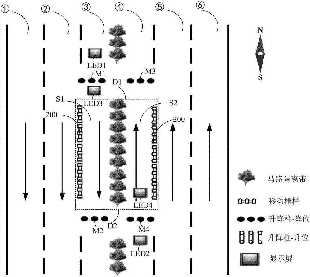
[0025] At present, the problem of road congestion in special time periods such as rush hours and holidays is relatively serious, which has brought great changes to people's lives. The inventor found through long-term observation that, for the above-mentioned special time period, among the two-way driving lanes, the lane in one driving direction is relatively congested, while the lane in the opposite driving direction is relatively free. Thinking from this phenomenon, the research has obtained the scheme of the embodiment of the present invention, setting shared lanes in the two-way lanes, intelligently changing the driving direction of the shared lanes according to the real-time utilization of the lanes, and alleviating traffic congestion by improving the utilization rate of the lanes question.
[0026] The following will clearly and completely describe the technical solutions in the embodiments of the present invention with reference to the accompanying drawings in the embodiments of the present invention. Obviously, the described embodiments are some of the embodiments of the present invention, but not all of them. The components of the embodiments of the invention generally described and illustrated in the figures herein may be arranged and designed in a variety of different configurations. Accordingly, the following detailed description of the embodiments of the invention provided in the accompanying drawings is not intended to limit the scope of the claimed invention, but merely represents selected embodiments of the invention. It should be noted that like numerals and letters denote similar items in the following figures, therefore, once an item is defined in one figure, it does not require further definition and explanation in subsequent figures.
[0027] An embodiment of the present invention provides a shared lane control system, which is applied to two-way lanes. The two-way lane includes a first lane and a second lane, and the driving directions of the first lane and the second lane are opposite. At least two adjacent lanes in the preset section of the two-way lane are set as shared lanes, and the at least two adjacent lanes include at least one first lane and at least one second lane. For example, if figure 1 As shown, when the two-way lanes include three first lanes ①, first lane ② and first lane ③ along the first direction and three second lanes ④, second lane ⑤ and second lane ⑥ along the second direction, The first lane ③ and the second lane ④ adjacent to the middle of the preset road section can be set as shared lanes. For another example, when the two-way lanes are all 4 lanes (4 first lanes and 4 second lanes), it is also possible to use the two first lanes and two second lanes adjacent to the middle in the preset road section, or Two first lanes and one second lane, or one first lane and two second lanes as shared lanes.
[0028] It should be noted that the specific numbers of the first lane and the second lane set as shared lanes may be set according to the number of the first lane and the second lane included in the two-way lane and the historical traffic conditions of the two-way lane.
[0029] It should also be noted that the aforementioned preset road section may be the entire road section of the two-way lane, or one of the road sections of the two-way lane, or a plurality of road sections distributed at intervals in the two-way lane. Of course, if the aforementioned preset road sections are a plurality of road sections distributed at intervals in the two-way lanes, the shared lane control system provided by this embodiment may be installed on the road sections where each shared lane is located.
[0030] like figure 2 As shown, the shared lane control system 100 provided by the embodiment of the present invention includes a control device 110 and a navigation device. like figure 1 As shown, D1 represents the first end of the shared lane, and D2 represents the second end of the shared lane. The navigation devices are respectively arranged at the first end D1 and the second end D2 of the shared lane. The navigation device includes a blocking device 120 and a display device 130 , each of which is coupled to the control device 110 .
[0031] The control device 110 obtains the first traffic flow detection values of all the first lanes and the second traffic flow detection values of all the second lanes, and judges the first lane and the second traffic flow according to the first traffic flow detection values and the second traffic flow detection values Whether the preset conditions are met. In this embodiment, the aforementioned preset condition may be a condition that either one of the first lane and the second lane is in a congested state and the other is in an idle state. For example, the first lane is in a congested state and the second lane is in an idle state, or the first lane is in an idle state and the second lane is in a congested state.
[0032] It should be noted that the blocking device 120 includes a blocking state and a passing state. In the initial state, the blocking devices 120 are all in the passing state. At this time, the driving direction of the shared lane on the side of the first lane is the first direction, which is consistent with the driving direction of the first lane; the driving direction of the shared lane on the side of the second lane is is the second direction, which is consistent with the driving direction of the second lane.
[0033] When the control device 110 determines that the first lane and the second lane meet the preset conditions, the control device 110 sends a first control instruction to the blocking device 120 corresponding to the shared lane in the idle lane. The blocking device 120 is used to block the corresponding shared lane according to the first control command sent by the control device 110, and change from the passing state to the blocking state, thereby changing the driving direction of the shared lane.
[0034] In addition, when the control device 110 determines that the first lane and the second lane meet the above-mentioned preset conditions, it is also used to send a second control instruction to the display device 130 to control the display device 130 to display corresponding instruction information, so as to prompt the first lane and the second lane The driver of the vehicle in the second lane pays attention to the driving direction of the shared lane ahead, so as to change lanes in time and avoid traffic accidents caused by the change of the driving direction of the shared lane.
[0035] When the control device 110 determines that the first lane and the second lane do not meet the above preset conditions, that is, both the first lane and the second lane are in a congested state or an idle state, or at least one of the first lane and the second lane is in a When there is neither congestion nor idle state, the current state of the blocking device 120 is detected. When the blocking device 120 is currently in the passing state, the control device 110 does not issue a control command. At this time, the blocking device 120 remains in the passing state and the display device 130 continues to display Current indication information; when the blocking device 120 is currently in the blocking state, the control device 110 controls the blocking device 120 to return from the blocking state to the passing state, and controls the display device 130 to change the currently displayed indication information accordingly.
[0036] In this embodiment, the control device 110 may be a chip with a data processing function such as a single chip microcomputer, DSP, ARM or FPGA.
[0037] In this embodiment, the blocking device 120 includes a first blocking device and a second blocking device. Both the first blocking device and the second blocking device are coupled to the control device 110 . Wherein, the first blocking device is a blocking device 120 arranged at the first end D1 and the second end D2 of each of the shared lanes on one side of the first lane, and the second blocking device is a blocking device 120 arranged at each side of the second lane. The blocking device 120 at the first end D1 and the second end D2 of the shared lane.
[0038] That is to say, when the control device 110 determines that the first lane is in a congested state and the second lane is in an idle state, it sends a first control command to the second blocking device to control the second blocking device's movement to the side of the second lane. The shared lane is blocked, so that the driving direction of the shared lane on the second lane side is changed from the second direction to the first direction. At this time, vehicles driving in the second lane cannot enter the shared lane, while vehicles driving in the first lane Vehicles can borrow the shared lane, thereby alleviating the traffic congestion problem of the first lane. Similarly, if the first lane is in an idle state and the second lane is in a congested state, send the first control command to the first blocking device to control the first blocking device to block the shared lane on the side of the first lane, so that the second lane The driving direction of the shared lane on the side of one lane is changed from the first direction to the second direction. At this time, the vehicles driving in the first lane cannot enter the shared lane, while the vehicles driving in the second lane can borrow the shared lane, thus Alleviate traffic congestion in the second lane.
[0039] Specifically, such as image 3 As shown, the blocking device 120 may include a driver 121 and an electric lifting column 122 , the control device 110 is coupled to the driver 121 , and the driver 121 is coupled to the electric lifting column 122 . The driver 121 is used to drive the electric lifting column 122 to rise according to the first control instruction so as to block the corresponding shared lane. In the above initial state, the electric lifting columns 122 included in the first blocking device and the second blocking device are all lowered; the driving direction of the shared lane on the first lane side is the first direction. It is said to be in a passing state; the driving direction of the shared lane on the second lane side is the second direction, and it is also in a passing state for vehicles driving in the second lane.
[0040] When the electric lifting columns 122 included in the first blocking device are all in the raised position, for vehicles traveling in the first lane, the shared lane on the side of the first lane is in a blocking state. At this time, the vehicles traveling in the second lane The shared lane on the first lane side and the shared lane on the second lane side can be occupied. Similarly, when the electric lifting columns 122 included in the second blocking device are all in the raised position, for vehicles traveling in the second lane, the shared lane on the side of the second lane is in a blocking state. At this time, in the first lane A traveling vehicle can occupy the shared lane on the first lane side and the shared lane on the second lane side. In this embodiment, the driver 121 may include a motor and an electrical appliance driving circuit. It should be noted that, in addition to the electric lifting column 122 mentioned above, other barrier structures may also be used in this embodiment.
[0041] In addition, when the control device 110 determines that the first lane and the second lane meet the above-mentioned preset conditions, it is also used to send a second control instruction to the display device 130 to control the display device 130 to display corresponding instruction information, so as to prompt the first lane and the second lane Drivers of vehicles in the second lane pay attention to the driving direction of the shared lane ahead in order to change lanes in time.
[0042] In this embodiment, the display device 130 includes a first display screen and a second display screen, and both the first display screen and the second display screen are coupled to the control device 110 . The first display screen is set at a first preset position, and the second display screen is set at a second preset position. Wherein, the first preset position is located on the side of the first lane, specifically behind the first blocking device provided at the first end D1 of the shared lane on the side of the first lane along the driving direction of the first lane. The second preset position is located on the side of the second lane, specifically behind the second blocking device provided at the second end D2 of the shared lane on the side of the second lane along the driving direction of the second lane. For example, the driving direction of the first lane is from north to south, and the driving direction of the second lane is from south to north, then the first preset position is located at the first blocking device set at the first end D1 of the shared lane on the side of the first lane The second preset position is located in the south of the second blocking device provided at the second end D2 of the shared lane on the side of the second lane.
[0043] Specifically, the first preset position can be set according to factors such as the average speed of the road section and the distance at which the driver of the vehicle driving on the first lane can clearly see the prompt information displayed on the first display screen, so that the driver can keep abreast of the distance ahead. Share lane usage and respond to it. Certainly, the setting of the second preset position is similar to the setting of the first preset position.
[0044] The first display screen is used to display the first prompt information according to the second control instruction sent by the control device 110 . The second display screen is used for displaying second prompt information according to the second control instruction sent by the control device 110 . Wherein, the first prompt information is used to prompt the driver of the vehicle driving on the first lane to use the shared lane in front, so as to change lane in time. The second prompt information is used to prompt the driver of the vehicle traveling on the second lane to use the shared lane in front, so as to change lane in time.
[0045]In order to facilitate the driver of the vehicle in the second lane occupying the shared lane on the side of the first lane and the driver of the vehicle in the first lane occupying the shared lane on the side of the second lane to know the usage of the shared lane in time, the display device 130 in this embodiment also A third display and a fourth display may be included. Both the third display screen and the fourth display screen are also coupled to the control device 110 . The third display screen is set at the third preset position, and the fourth display screen is set at the fourth preset position. The third preset position is located at the first end D1 of the shared lane on the first lane side, and the fourth preset position is located at the second end D2 of the shared lane on the second lane side. Similarly, the third preset position and the fourth preset position can also be set according to actual conditions. For example, when the driving direction of the first lane is from north to south, and the driving direction of the second lane is from south to north, the third preset position can be located on the side of the first lane, specifically on the shared lane on the side of the first lane. South of the first blocking device set at one end D1 and close to the first blocking device, the fourth preset position may be located on the second lane side, specifically at the second end D2 of the shared lane on the second lane side. North of the second blocking device and close to the second blocking device.
[0046] The third display screen is used for displaying third prompt information according to the second control instruction sent by the control device 110 . The fourth display screen is used to display fourth prompt information according to the second control instruction sent by the control device 110 . Wherein, the third prompt information is used to remind the driver of the vehicle occupying the second lane of the shared lane on the side of the first lane that the use of the shared lane is about to end, so as to change back to the original lane in time. The fourth prompt information is used to remind the driver of the vehicle occupying the first lane of the shared lane on the side of the second lane that the use of the shared lane is about to end, so as to change back to the original lane in time.
[0047] In this embodiment, the first display screen, the second display screen, the third display screen and the fourth display screen may be LED display screens or liquid crystal display screens.
[0048] As an implementation manner, the first threshold and the second threshold may be preset in the control device 110 . When the detected value of the traffic flow exceeds the first threshold, it indicates that the lane is in a congested state, and when the detected value of the traffic flow is lower than the second threshold, it indicates that the lane is in an idle state. Wherein, the first threshold and the second threshold can be set by the traffic department, and can be modified according to the actual situation, and can also be updated every day. At this time, the step of judging whether the first lane and the second lane meet the preset condition according to the first traffic flow detection value and the second traffic flow detection value may include:
[0049] Judging whether the first traffic flow detection value and the second traffic flow detection value satisfy whether the first traffic flow detection value is greater than the first threshold and the second traffic flow detection value is less than the preset second threshold, or the first traffic flow detection value is less than the first threshold Two thresholds and the second traffic flow detection value is greater than the first threshold;
[0050] When the first traffic flow detection value is greater than the first threshold and the second traffic flow detection value is less than the second threshold, it is determined that the first lane is in a congested state and the second lane is in an idle state, meeting the preset condition;
[0051] When the first traffic flow detection value is less than the second threshold and the second traffic flow detection value is greater than the first threshold, it is determined that the first lane is in an idle state and the second lane is in a congested state, and the preset condition is met;
[0052] When the first traffic flow detection value and the second traffic flow detection value are both greater than the first threshold, it is determined that both the first lane and the second lane are in a congested state and do not meet the preset condition;
[0053] When the first traffic flow detection value and the second traffic flow detection value are both smaller than the second threshold value, it is determined that both the first lane and the second lane are in an idle state and do not meet the preset condition;
[0054] When at least one of the first traffic flow detection value and the second traffic flow detection value is greater than the second threshold and less than the first threshold, it is determined that at least one of the first lane and the second lane is in a state that is neither congested nor idle. Meet the preset conditions.
[0055] As another implementation, for two-way lanes with a large number of lanes, when the number of shared lanes set on the first lane side and the number of shared lanes set on the second lane side are both greater than or equal to two, it is also possible Set two levels of congestion state and one level of idle state, and control the number of shared lanes occupying the side of the lane in idle state according to the congestion level of the lane in the state of congestion. At this time, the first threshold and the second threshold may be set in the control device 110 in advance, the first threshold includes a primary congestion threshold and a secondary congestion threshold, and the primary congestion threshold is greater than the secondary congestion threshold. When the traffic flow detection value is greater than the first-level congestion threshold, it means that the lane is in the first-level congestion state; When the flow detection value is lower than the second threshold, it indicates that the lane is in an idle state. Wherein, the first-level congestion threshold, the second-level congestion threshold, and the second threshold can be set by the traffic department, and can be modified according to actual conditions. Take two shared lanes on the side of the first lane and the side of the second lane as an example, at this time, judge whether the first lane and the second lane meet the preset conditions according to the first traffic flow detection value and the second traffic flow detection value The steps can include:
[0056] Judging whether the first traffic flow detection value and the second traffic flow detection value satisfy whether the first traffic flow detection value is greater than the secondary congestion threshold and the second traffic flow detection value is less than the second threshold, or the first traffic flow detection value is smaller than the second threshold And the second traffic flow detection value is greater than the secondary congestion threshold;
[0057] When the first traffic flow detection value is greater than the second level congestion threshold and the second traffic flow detection value is less than the second threshold, continue to judge whether the first traffic flow detection value is greater than the first level congestion threshold;
[0058] When the first traffic flow detection value is greater than the first-level congestion threshold, it is determined that the first lane is in a first-level congestion state, and the second lane is in an idle state, and the preset conditions are met, and the first control command is sent to the second blocking device. Both shared lanes on the side of the lane are blocked. At this time, for the vehicles driving in the second lane, the two shared lanes on the side of the second lane are blocked and cannot pass through, while the vehicles driving in the first lane can occupy the two shared lanes on the side of the first lane. the shared lane and the two shared lanes on the side of the second lane;
[0059] When the first traffic flow detection value is less than the first-level congestion threshold, it is determined that the first lane is in the second-level congestion state, the second lane is in an idle state, and the preset conditions are met, and the first control command is sent to the second blocking device. A shared lane on the side of the lane close to the side of the first lane is blocked. At this time, for vehicles traveling in the second lane, a shared lane on the side of the second lane close to the first lane is in a blocking state and cannot pass, while the other shared lane is in a passing state and can pass. Vehicles traveling in the first lane may occupy two shared lanes on the side of the first lane and one shared lane on the side of the second lane close to the side of the first lane.
[0060] It can be understood that, when the first traffic flow detection value is smaller than the second threshold and the second traffic flow detection value is greater than the secondary congestion threshold, the process is similar to the above process and will not be repeated here.
[0061] When the first traffic flow detection value and the second traffic flow detection value do not meet the above-mentioned threshold conditions, it means that the first lane and the second lane are all in a congested state (including a first-class congested state and a second-class congested state), or the first Both the lane and the second lane are in an idle state, or at least one of the first lane and the second lane is neither in a congested state nor in an idle state, at this time it is determined that the first lane and the second lane do not meet the preset condition.
[0062] It should be noted that, in addition to the above-mentioned way of setting two levels of congestion status and one level of idle status, other ways can also be used, for example, two or more levels of congestion status and two or more levels of idle status can also be set. Status, the specific principle is similar to the above judgment process, and will not be described in detail here.
[0063] In this embodiment, the control device 110 may have various implementation manners for obtaining the first detected traffic flow values of all first lanes and the second detected traffic flow values of all second lanes.
[0064] As an implementation, the control device 110 can receive the traffic flow information sent by the traffic flow detection system set up by the traffic department on a specific road section, including the first traffic flow detection values of all first lanes and all second lanes of the specific road section. Traffic flow detection value.
[0065] As another implementation, such as image 3 As shown, the shared lane control system 100 provided by the embodiment of the present invention may further include a traffic flow detection device 140 , and the traffic flow detection device 140 is coupled with the control device 110 . The traffic flow detection device 140 is used to collect the first traffic flow information of all the first lanes and the second traffic flow information of all the second lanes, and collect the first traffic flow information and the second traffic flow information sent to the controller 110. At this time, the control device 110 is further configured to obtain a first detected traffic flow value according to the first traffic flow information, and obtain a second detected traffic flow value according to the second traffic flow information.
[0066] In this embodiment, the traffic flow detection device 140 can be mainly divided into the following two categories. One is a fixed detection device, and the other is a mobile detection device.
[0067] Specifically, the traffic flow detection device 140 can be a video acquisition device such as a camera, which can collect driving video of the road through the video acquisition device installed on a specific section of the two-way lane, and obtain vehicle information in the driving video through image processing technology. The vehicle information includes first traffic flow information of all first lanes and second traffic flow information of all second lanes. In addition, the traffic flow detection device 140 can also be a magnetic induction coil, and the magnetic induction coil is laid as a sensor at the detection position in the specific road section of the two-way lane, and the magnetic induction coil is connected to the oscillating circuit. When a vehicle passes above the magnetic induction coil, The iron shell of the vehicle causes the inductance of the magnetic induction coil to change, and the change in inductance is converted into a change in the resonant frequency of the oscillating circuit, which is converted into a digital signal and sent to the control device 110 as traffic flow information. The detected value of the traffic flow can be obtained by counting the changes of the resonant frequency in the information. Wherein, the first traffic flow detection value obtained according to the first traffic flow information correspondingly output by the magnetic induction coils provided at the detection positions of all the first lanes in the specific road section of the two-way lane is the first traffic flow detection value; The magnetic induction coils installed at the detection positions of all the second lanes correspond to the output of the second traffic flow information to obtain the second traffic flow detection value as the second traffic flow detection value.
[0068] When the traffic flow detection device 140 is a mobile detection device, the first traffic flow information can be obtained by collecting the vehicle running conditions of all the first lanes in the specific road section of the two-way lane based on the positioning of GPS, and collecting the vehicle traffic information in the specific road section of the two-way lane. The traffic conditions of all the vehicles in the second lane are used to obtain the second traffic flow information.
[0069] Of course, in addition to the above methods, the vehicle flow detection device 140 provided in this embodiment may also use detection devices corresponding to other existing traffic flow detection technologies, which will not be repeated here.
[0070] It should be noted that, assuming that the driving direction of the two-way lane is north-south, the driving direction of the first lane is from north to south, and the driving direction of the second lane is from south to north. At this time, for the first lane, the above-mentioned specific road section should be a road section with a specific length that is connected to the road section of the shared lane on the side of the first lane and located in the north of the shared lane; for the second lane, the above-mentioned specific road section should be the same as The road section where the shared lane on the second lane side is connected and located in the south of the shared lane is a road section with a specific length. And the traffic flow detection point in this specific road section should be set at a certain distance from the shared lane. The distance should be based on the response time of the blocking device 120 and the display device 130, the average speed of the road section, and the driver's ability to see the display device 130 clearly. The distance and other factors of the prompt information displayed on the vehicle are set so that the driving direction of the shared lane ahead can be adjusted in time and the prompt information can be given.
[0071] In addition, in order to improve safety, a fence 200 may be set between the above-mentioned shared lane and other first lanes and second lanes other than the shared lane, so as to isolate the common lane and the shared lane. Preferably, the fence 200 is a movable fence.
[0072] In order to make the technical solution of the shared lane control system 100 provided by the embodiment of the present invention clearer, the following figure 1 A specific application scenario shown is taken as an example to illustrate the use of the shared lane control system 100 provided in this embodiment.
[0073] figure 1 A two-way six-lane road segment is shown. like figure 1 As shown, the driving direction of the first lane in this road section is from north to south, and the driving direction of the second lane is from south to north. figure 1 The symbol N in the symbol means north, and the symbol S means south. In the figure, LED1 represents the first display screen, LED2 represents the second display screen, LED3 represents the third display screen, and LED4 represents the fourth display screen. Wherein, the display areas of the first display LED1 and the fourth display LED4 face north, and the display areas of the second display LED2 and the third display LED3 face south. M1 represents the electric lifting column 122 (control device 110 and driver 121) that is included in the first blocking device at the first end D1 of the shared lane S1 on the first lane side. figure 1 not shown in ), M2 represents the electric lifting column 122 included in the first blocking device arranged at the second end D2 of the shared lane S1 on the first lane side, and M3 means the electric lifting column 122 included in the shared lane S2 arranged on the second lane side The electric lifting column 122 included in the second blocking device at one end D1, and M4 represents the electric lifting column 122 included in the second blocking device at the second end D2 of the shared lane S2 on the second lane side. The area where the dotted frame is located includes the shared lane S1 on the first lane side and the shared lane S2 on the second lane side.
[0074] When the control device 110 determines that the first lane and the second lane are both in a congested state or in an idle state, as figure 1 As shown, the electric lifting columns M1, M2, M3, and M4 are all lowered, the shared lane remains unchanged, and the original road planning is maintained, that is, the driving direction of the shared lane S1 on the first lane side is from north to south, and on the second lane side The driving direction of the shared lane S2 is from south to north. At this time, the first display LED1 and the second display LED2 can both display "please go straight", and the third display LED3 and the fourth display LED4 do not display any information. information.
[0075] When the control device 110 determines that the first lane is in a congested state and the second lane is in an idle state, the control device 110 controls the electric lifting columns M3 and M4 to rise, so that both M3 and M4 are raised, and M1 and M2 are still lowered. like Figure 4 As shown, at this time, the driving direction of the shared lane S1 on the first lane side is from north to south, and the driving direction of the shared lane S2 on the second lane side is also changed from north to south. At this time, vehicles traveling in the first lane may occupy the shared lane S1 and the shared lane S2. The control device 110 can control the first display LED1 to display "a meter ahead, the shared lane can be borrowed", the second display LED2 displays "the shared lane is occupied at B meters ahead, please change the lane", and the third display LED3 does not display any information, and the fourth display LED4 displays "the use of the shared lane is about to end, please change back to the original lane". Among them, "A meter" is set according to the distance between the setting position of the first display screen and the first end of the shared lane on the first lane side, and "B meter" is set according to the setting position of the second display screen and the shared lane on the second lane side. The distance setting for the second end of the . After the traffic in the first lane is alleviated, that is, when it is determined that the first lane and the second lane do not meet the above-mentioned preset conditions, the control device 110 controls the electric lifting columns M3 and M4 to reset (lower), as figure 1 As shown, and control the first display screen LED1 and the second display screen LED2 to display "please go straight", the third display screen LED3 and the fourth display screen LED4 do not display any information.
[0076] When the control device 110 determines that the first lane is in an idle state and the second lane is in a congested state, the control device 110 controls the electric lifting columns M1 and M2 to rise so that both M1 and M2 are raised, and M3 and M4 remain lowered. like Figure 5 As shown, at this time, the driving direction of the shared lane S1 on the first lane side is changed from south to north, and the driving direction of the shared lane S2 on the second lane side is still from south to north. At this time, vehicles traveling in the second lane may occupy the shared lane S1 and the shared lane S2. The control device 110 can control the first display LED1 to display "A meter ahead, the shared lane is occupied, please change lane", the second display LED2 displays "B meters ahead, the shared lane can be borrowed", and the third display LED3 displays "the use of the shared lane is about to end, please change back to the original lane", and the fourth display LED4 does not display any information. After the traffic in the second lane is alleviated, that is, when it is determined that the first lane and the second lane do not meet the above-mentioned preset conditions, the control device 110 controls the electric lifting columns M1 and M2 to reset (lower), as figure 1 As shown, and control the first display screen LED1 and the second display screen LED2 to display "please go straight", the third display screen LED3 and the fourth display screen LED4 do not display any information.
[0077] To sum up, the shared lane control system 100 provided by the embodiment of the present invention creatively proposes to set at least two adjacent lanes in the preset section of two-way lanes as shared lanes, and the at least two adjacent lanes include at least One first lane and at least one second lane, the first traffic flow detection value of all first lanes and the second traffic flow detection value of all second lanes are obtained by the control device 110, according to the first traffic flow detection value and the second traffic flow detection value When the traffic flow detection value determines that the first lane and the second lane meet the preset conditions, control the blocking device 120 corresponding to the shared lane in the idle lane to block the shared lane, so as to change the driving direction of the shared lane, and The display device 130 is controlled to display corresponding instruction information. By changing the driving direction of the shared lane corresponding to the idle lane in the two-way lane, it is easy to relieve the driving pressure of the congested lane in the two-way lane, thereby effectively alleviating the problem of road congestion during the peak travel period and reducing the burden on the traffic police.
[0078] In addition, an embodiment of the present invention also provides a shared lane control method, which is applied to the control device 110 in the above shared lane control system 100, such as Image 6 As shown, the method includes:
[0079] Step S101, acquiring first traffic flow detection values of all first lanes and second traffic flow detection values of all second lanes;
[0080] Step S102, judging whether the first lane and the second lane meet a preset condition according to the first traffic flow detection value and the second traffic flow detection value;
[0081] Wherein, the preset condition is a condition that any one of the first lane and the second lane is in a congested state and the other is in an idle state;
[0082] Step S103, when the preset condition is met, send a first control instruction to the blocking device corresponding to the shared lane in the lane in the idle state, so that the blocking device Instructions to block the corresponding shared lane and change the driving direction of the shared lane;
[0083] Step S104, sending a second control command to the display device 130 to control the display device 130 to display corresponding instruction information.
[0084] Specifically, step S102 may include:
[0085] Judging whether the first traffic flow detection value and the second traffic flow detection value satisfy whether the first traffic flow detection value is greater than the preset first threshold and the second traffic flow detection value is smaller than the preset second threshold, or the first traffic flow detection The value is less than the second threshold and the second traffic flow detection value is greater than the first threshold;
[0086] When the first traffic flow detection value is greater than the first threshold and the second traffic flow detection value is less than the second threshold, it is determined that the first lane is in a congested state and the second lane is in an idle state, meeting the preset condition;
[0087] When the first traffic flow detection value is less than the second threshold and the second traffic flow detection value is greater than the first threshold, it is determined that the first lane is in an idle state and the second lane is in a congested state, and the preset condition is met;
[0088] When the first traffic flow detection value and the second traffic flow detection value are both greater than the first threshold, it is determined that both the first lane and the second lane are in a congested state and do not meet the preset condition;
[0089] When the first traffic flow detection value and the second traffic flow detection value are both smaller than the second threshold value, it is determined that both the first lane and the second lane are in an idle state and do not meet the preset condition;
[0090] When at least one of the first traffic flow detection value and the second traffic flow detection value is greater than the second threshold and less than the first threshold, it is determined that at least one of the first lane and the second lane is in a state that is neither congested nor idle. Meet the preset conditions.
[0091] Those skilled in the art can clearly understand that for the convenience and brevity of the description, the specific working process of the method described above can refer to the corresponding process in the aforementioned system, device and unit embodiments, and will not be repeated here.
[0092] In the description of the present invention, it should be noted that the orientation or position indicated by the terms "center", "upper", "lower", "left", "front", "rear", "inner", "outer" etc. The relationship is based on the orientation or positional relationship shown in the drawings, or the orientation or positional relationship that the inventive product is usually placed in use, and is only for the convenience of describing the present invention and simplifying the description, rather than indicating or implying the referred device or Elements must have certain orientations, be constructed and operate in certain orientations, and therefore should not be construed as limitations on the invention. In addition, the terms "first", "second", etc. are only used for distinguishing descriptions, and should not be construed as indicating or implying relative importance.
[0093] In the description of the present invention, it also needs to be explained that, unless otherwise clearly specified and limited, the terms "set", "coupled" and "connected" should be interpreted in a broad sense, for example, they can be directly connected or can be connected through an intermediate A media indirect connection can be an internal connection between two elements. Those of ordinary skill in the art can understand the specific meanings of the above terms in the present invention according to specific situations.
[0094] The above descriptions are only preferred embodiments of the present invention, and are not intended to limit the present invention. For those skilled in the art, the present invention may have various modifications and changes. Any modifications, equivalent replacements, improvements, etc. made within the spirit and principles of the present invention shall be included within the protection scope of the present invention.
PUM


Description & Claims & Application Information
We can also present the details of the Description, Claims and Application information to help users get a comprehensive understanding of the technical details of the patent, such as background art, summary of invention, brief description of drawings, description of embodiments, and other original content. On the other hand, users can also determine the specific scope of protection of the technology through the list of claims; as well as understand the changes in the life cycle of the technology with the presentation of the patent timeline. Login to view more.