One-belt one-way electric telescopic door

An electric telescopic, one-belt technology, applied in the directions of windows/doors, gates/doors, door/window accessories, etc., can solve the problems that the guide rod is not easy to fix, the overall length is limited, and the technical requirements for the installation of the guide rod are high, so as to ensure wind resistance. and stability, convenient production and processing, and remarkable operation effect.

Active Publication Date: 2017-07-14
南京厚和机电科技有限公司 +1
View PDF9 Cites 4 Cited by
  • Summary
  • Abstract
  • Description
  • Claims
  • Application Information

AI Technical Summary

Problems solved by technology

Defects: The overall length of each door section of this type of door is limited due to the increasing or decreasing height and width; some door sections are small in area and lack aesthetic feeling
Disadvantages: The retractable door relies on the guide wheel mechanism to realize the expansion and contraction of the door body. The transmission method is one section to pull the other section. Reset to each other, and finally tolerate each other
Defect: The door body is thin, and the whole door is expanding or shrinking at the same time when opening and closing the door, resulting in insufficient stability of the door body movement
The defect of the present invention is that the guide rod of the guide device has serious friction when the retractable door is folded or unfolded; and the guide rod of the guide device requires high installation technology, the guide rod of the guide device is not easy to fix, and its length is greatly limited. Therefore, Telescopic doors usually need to install more guide rods for guide devices

Method used


Image

  • One-belt one-way electric telescopic door
  • One-belt one-way electric telescopic door
  • One-belt one-way electric telescopic door

Examples


Embodiment 1

[0042] [Example 1] One belt and one road electric telescopic door.

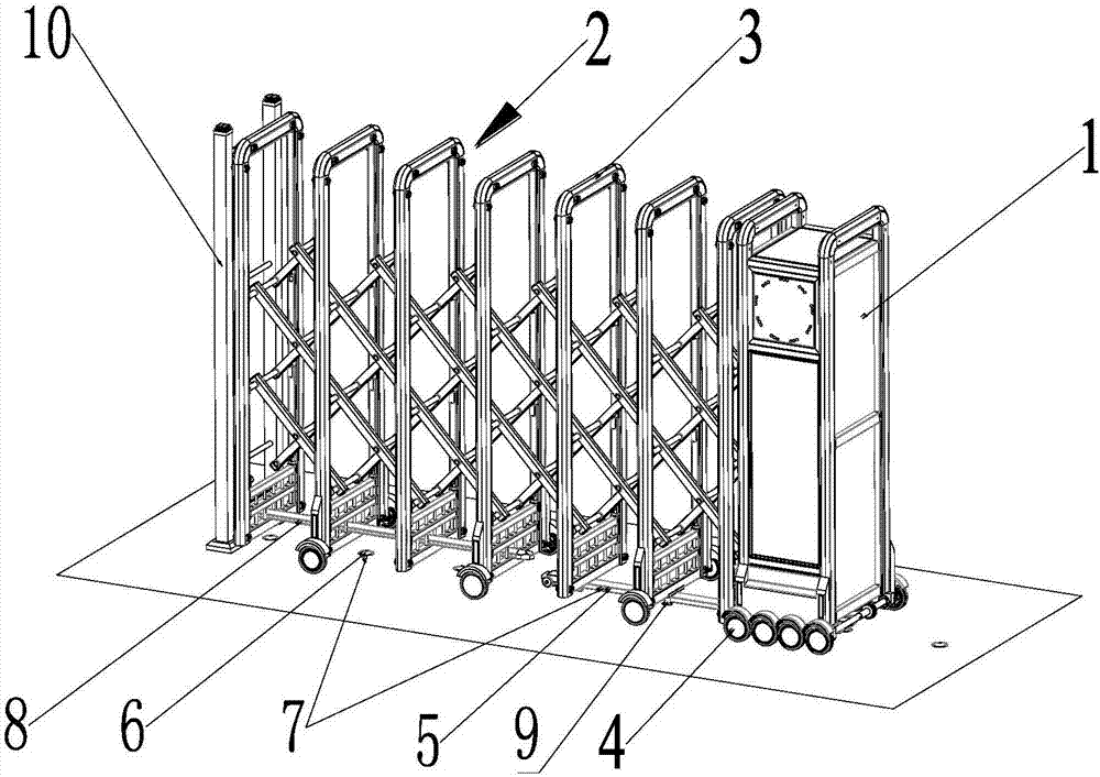
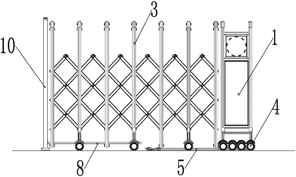
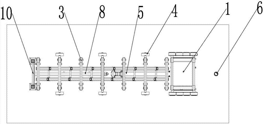
[0043] Such as figure 1 Shown is a schematic diagram of the overall structure of the telescopic door of this embodiment, an electric telescopic door along the Belt and Road, which includes an electromechanical door head 1, a door body 2 connected to the door head, and walking wheels installed under the electromechanical door head 1 and the door body 2 4. The door body 2 is composed of several door frames 3, which all belong to the characteristics of the prior art. The inventive point of the present invention is that: the electromechanical door head 1 and the lower part of the door body 2 are provided with a guide rod assembly 5 and a guide rod assembly Corresponding dot-like distribution of invisible rail assemblies 6, the guide rod assembly 5 is installed on the electromechanical door head 1, the invisible rail assembly 6 is buried in the ground, the guide rod assembly 5 and the invisible rail The component...

Embodiment 2

[0048] [Example 2] The guide rod assembly for the electric telescopic door along the Belt and Road.

[0049] Figure 4-7 It is a schematic diagram of the overall structure of the guiding device of the embodiment of the present invention. The guide device 7 is composed of the guide rod assembly 5 and the invisible rail assembly 6 which are dynamically matched with each other.

[0050] The guide rod assembly for the One Belt One Road electric telescopic door in this embodiment is a groove-shaped concave rail 51, and the groove-shaped concave rail 51 is divided into three sections, the middle section 52 is relatively fixed, the front end section 53 and the rear end section 54 floats up and down within a certain angle with respect to the middle section 52 , and the three sections pass through together to form the groove-shaped concave rail 51 . The front end section 53 and the rear end section 54 of the grooved concave rail are also provided with rollers 55, and the heads of the...

Embodiment 3

[0054] [Example 3] The invisible rail assembly for electric telescopic doors along the Belt and Road.

[0055] Figure 11 It is the overall outline view of the invisible rail assembly of Embodiment 3 of the present invention. Figure 12 It is a side plan view of the invisible rail assembly of Embodiment 3 of the present invention.

[0056] The guide rod assembly for the Belt and Road electric telescopic door of this embodiment is an invisible rail assembly for the Belt and Road electric telescopic door. Composition; the fixed shaft 64, the liftable column 63, the positioning ring 62, and the housing 61 are arranged sequentially from the inside to the outside, the upper cover 65 is arranged on the top of the housing 61, the positioning ring 62, the lifting column 63 . The fixed shaft 64 is placed in the housing 61 . The liftable column 63 has a convex column head 66, or a concave column head. The positioning ring 62 is formed by butt-jointing and assembling of two half-ring...


PUM


Abstract

The invention discloses a one-belt one-way electric telescopic door, comprising an electromechanical door head, a door body and walking wheels, wherein the door body is connected with the door head; the walking wheels are arranged below the door head and the door body; the door body is composed of a plurality of door frames; the lower part of each of the electromechanical door head and the door body is provided with guiding rod components and hidden rail components which are distributed in a point shape manner corresponding to the guiding rod components; each guiding rod component is arranged on the electromechanical door head; each hidden rail component is embedded in the ground; the guiding rod components and the hidden rail components are mutually matched dynamically, so that a guiding device is formed; the electromechanical door head drives the door body to extend or contract; the electromechanical door head and the door body maintain in a linear running state by utilization of the guiding device. The electric telescopic door disclosed by the invention has the advantages that the power transmission is unique, the running effect is significant, and the assembly and maintenance are convenient; during the process of opening and closing the door, the hidden rail components are enabled point by point through the guiding rod components, and the door body moves freely; the guiding rod components are matched with the hidden rail components, so that the wind resistance and stability of the telescopic door are guaranteed.

Description

technical field [0001] The invention relates to an electric telescopic door, in particular to a new product electric telescopic door with invisible tracks. Background technique [0002] At present, due to the beautiful and exquisite features of the electric telescopic door series products, which are convenient to open and close, they have been widely used in the courtyard doors of government agencies, colleges, factories and residential quarters, and with the rapid development of social and economic construction, Its market demand is increasing. To sum up, all types of automatic doors today can basically be divided into four categories: the first category is based on the working principle of vertical door row and chute structure, and the electric telescopic forms with different shapes and styles are derived. The form of electronically controlled telescopic doors; the second category is screen-type telescopic doors composed of door frames, screen pieces, hinges, rollers, etc...

Claims


Application Information

Patent Timeline
Patent Type & Authority Applications(China)
IPC IPC(8): E06B11/04E06B7/16E05D13/00E05D15/06E05F15/632
CPCE05D13/00E05D15/0665E05F15/632E05Y2900/40E06B7/16E06B11/045
Inventor 杨帆臧铁钢王鹏
Owner 南京厚和机电科技有限公司
Why Eureka
Try Eureka