A steady flow valve for a pump

A technology for steady flow valve and pump, which is applied in the direction of fluid pressure actuating device, servo motor assembly, mechanical equipment, etc. It can solve the problem of inability to ensure the normal operation of the main engine, difficult to meet the stable speed and steering stability of the main engine, and inability to ensure the hydraulic system. Stable flow and other issues, to meet the requirements of stable speed and steering stability, ensure normal operation, and maintain stable output flow

Active Publication Date: 2018-10-19
四川长江液压件有限责任公司
View PDF10 Cites 0 Cited by
  • Summary
  • Abstract
  • Description
  • Claims
  • Application Information

AI Technical Summary

Problems solved by technology

[0002] At present, when the oil supply volume of the oil pump and the load of the hydraulic system change, its output flow will change accordingly, and the stable flow required by the hydraulic system cannot be guaranteed, and it is difficult to meet the requirements of the stable speed and steering stability of the main engine. normal work

Method used


Image

  • A steady flow valve for a pump
  • A steady flow valve for a pump
  • A steady flow valve for a pump

Examples


Embodiment Construction

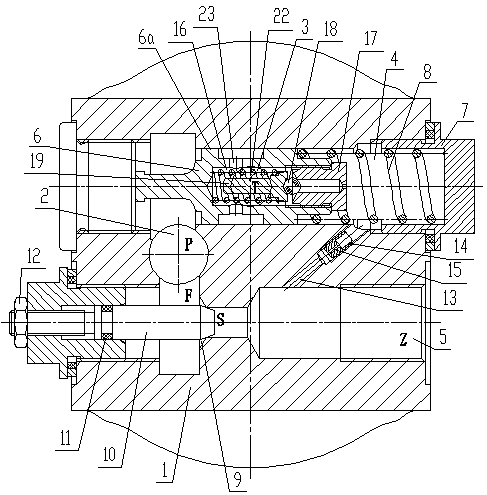
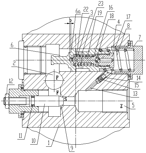
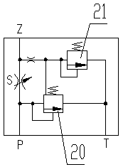
[0015] The present invention will be described in further detail below in conjunction with the accompanying drawings.

[0016] like Figure 1 to Figure 3 As shown, a steady flow valve for a pump in this embodiment includes a valve body 1, an oil inlet 2 (P) and an oil return port 3 (T) arranged in the valve body 1, and the valve body 1 is also provided with The steady-flow spring chamber 4 and the output oil passage 5 are both connected to the oil inlet 2. The steady-flow valve core 6 slides in the steady-flow spring chamber 4. The steady-flow valve core 6 is provided with a piston section 6a, and the piston section 6a It is located between the oil return port 2 and the oil inlet port 3; on the valve body 1 behind the steady flow valve core 6, a steady flow valve seat 7 is threaded, and between the steady flow valve core and the 6 steady flow valve seat 7 There is a return spring 8 between them, and the three form a pressure relief valve 20; an orifice 9 (S) is provided in th...


PUM


Abstract

The invention discloses a current stabilization valve for a pump. The current stabilization valve comprises a valve body, an oil inlet and an oil return port formed in the valve body; a current stabilization spring cavity and an output oil way connected with the oil inlet are also arranged in the valve body; a current stabilization valve element is slidingly arranged in the current stabilization spring cavity, and is provided with a piston section; the piston section is arranged between the oil return port and the oil inlet; a current stabilization valve base is connected to the valve body behind the current stabilization valve element; a return spring is arranged between the current stabilization valve element and the current stabilization valve base; a throttling port is formed in the output oil way; the output oil way behind the throttling port is connected with the current stabilizing spring cavity behind the current stabilization valve element through a connecting hole; a blind hole is formed in the back section of the current stabilization valve element; a pressure limiting valve is arranged in the blind hole; and the front section of the blind hole is connected with the oil return port through a radial hole. When the oil supply quantity of an oil pump and the load of a hydraulic system are changed, the current stabilization valve can basically keep the output flow stable to meet the requirements of stable rotating speed and steering stability of a host machine so as to guarantee normal work of the host machine.

Description

technical field [0001] The invention relates to a steady flow valve, in particular to a steady flow valve for a pump. Background technique [0002] At present, when the oil supply volume of the oil pump and the load of the hydraulic system change, its output flow will change accordingly, and the stable flow required by the hydraulic system cannot be guaranteed, and it is difficult to meet the requirements of the stable speed and steering stability of the main engine. normal work. Contents of the invention [0003] The purpose of the present invention is to solve the above-mentioned shortcomings in the prior art, and provide a steady flow valve for pumps, which can keep the output flow basically stable when the oil supply volume of the oil pump and the load of the hydraulic system change, and meet the requirements of the stable speed and steering of the main engine. Stability requirements to ensure the normal work of the host. [0004] In order to achieve the above object...

Claims


Application Information

Patent Timeline
Patent Type & Authority Patents(China)
IPC IPC(8): F15B13/02
CPCF15B13/021
Inventor 吕林其欧常斌王夏金
Owner 四川长江液压件有限责任公司
Why Eureka
Try Eureka