Eureka AIR delivers breakthrough ideas for toughest innovation challenges, trusted by R&D personnel around the world.

Pneumatic tensioning wheel device

A tensioner device, pneumatic technology, applied in the direction of transmission, belt/chain/gear, mechanical equipment, etc., can solve the problems of reduced shock absorption capacity of the tensioner, abnormal belt wear, reduced durability, etc., to avoid The effect of reduced shock absorption, elimination of loose mounting bolts, and optimized response speed

Pending Publication Date: 2018-12-04
ANHUI JIANGHUAI NAVISTAR DIESEL ENGINE CO LTD
View PDF6 Cites 0 Cited by
  • Summary
  • Abstract
  • Description
  • Claims
  • Application Information

AI Technical Summary

Problems solved by technology

[0004] 1. Using the spring as the return mechanism of the tensioner, it is difficult to monitor the tension force, and it is impossible to find the abnormal tension force at the first time. Excessive tension force may cause abnormal wear of the belt, and too small tension force may cause Belt slipping, wear, toothed belt jumping, reduction in transmission efficiency, etc.
[0005] 2. After the square damper is gradually worn out during use, the gap with the cover plate will gradually increase, which will reduce the shock absorption capacity of the tensioner, increase the vibration amplitude, and reduce the durability
[0006] 3. The bottom of the mandrel and the bottom of the shell in the existing scheme are usually flush. If the mandrel contacts the mounting surface during the tightening of the mounting bolts, false torque may be caused, that is, the shell is not pressed tightly, and the pressing force is reduced. , causing the mounting bolts to loosen during use

Method used


Image

  • Pneumatic tensioning wheel device
  • Pneumatic tensioning wheel device
  • Pneumatic tensioning wheel device

Examples


Embodiment Construction

[0037] The embodiments of the present invention are described in detail below. This embodiment is implemented on the premise of the technical solution of the present invention, and detailed implementation methods and specific operating procedures are provided, but the protection scope of the present invention is not limited to the following implementation example.

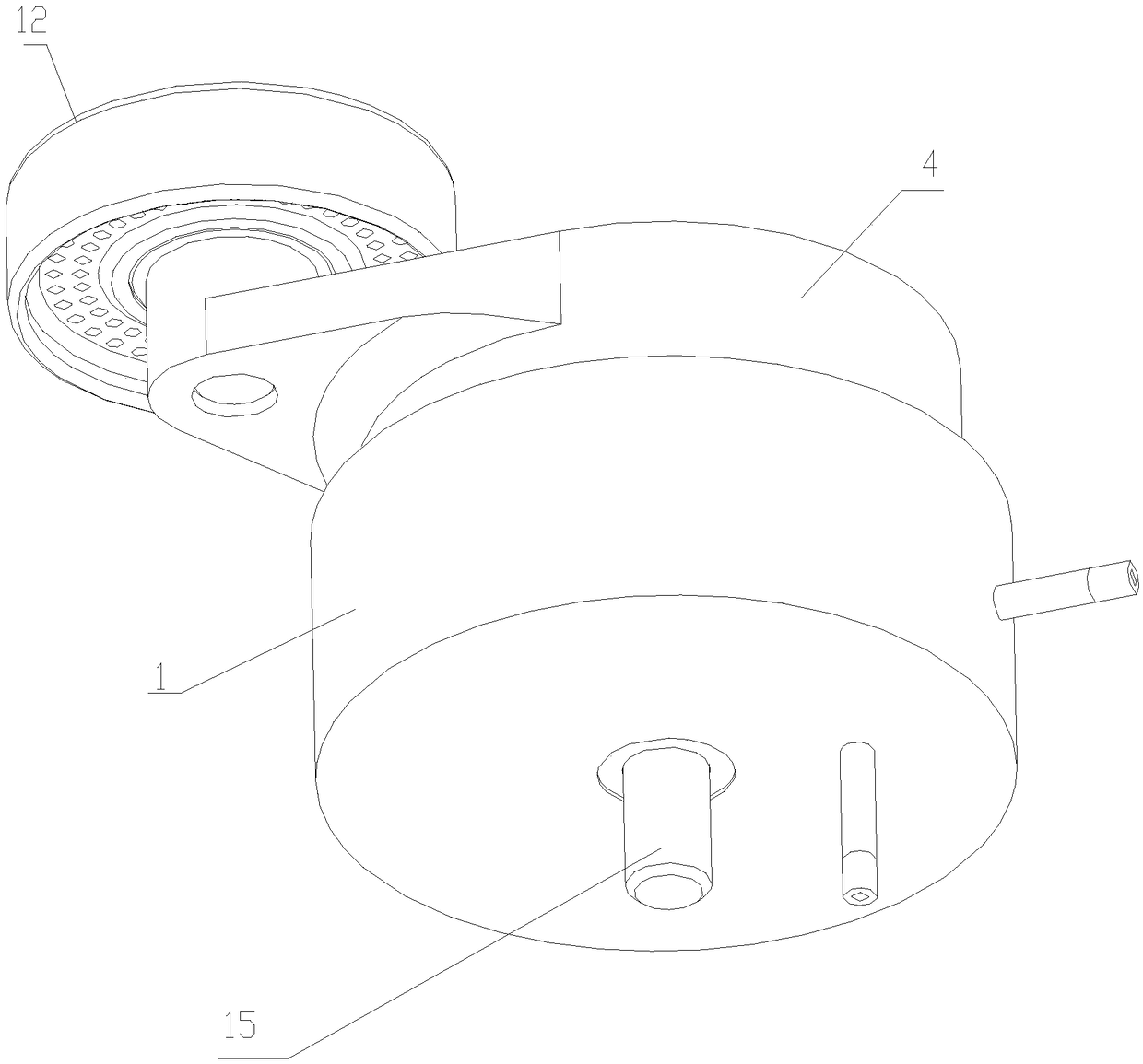
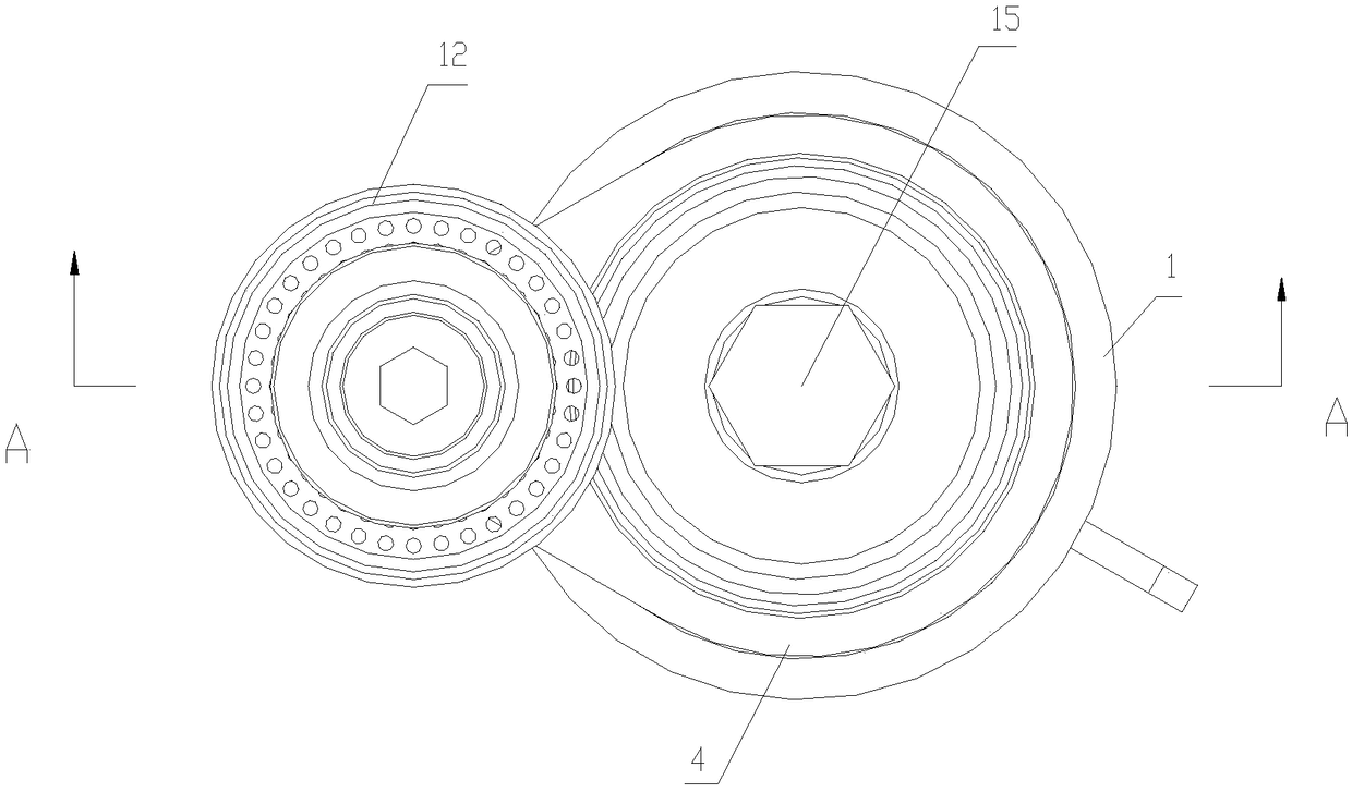
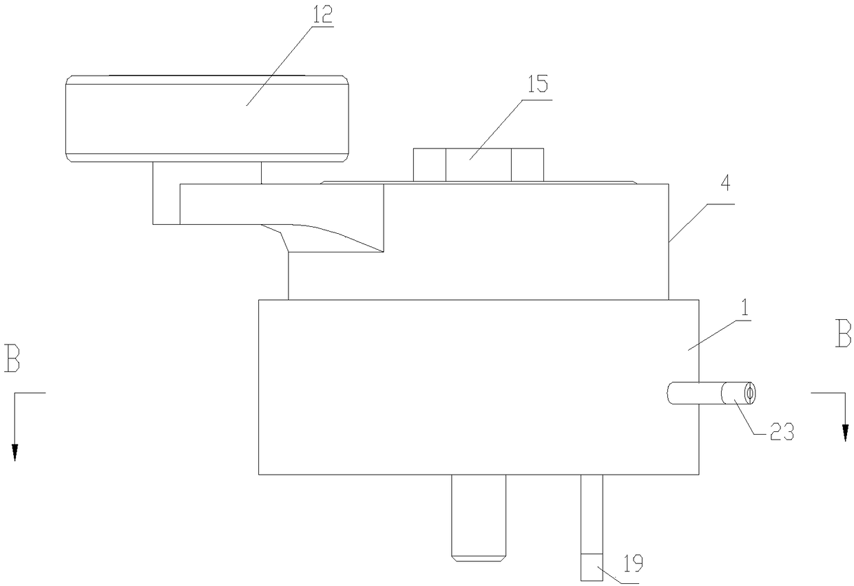
[0038] see Figure 1 to Figure 8 , this embodiment discloses a pneumatic tensioner device, which includes a cylindrical shell 1 with an opening at the top of the shell 1, and a mandrel extending vertically upward is fixed in the center hole of the bottom wall of the cavity of the shell 1 2. The bottom end surface of mandrel 2 is about 0.5mm higher than the bottom end surface of housing 1, which can prevent the mandrel 2 from contacting other supports when the mounting bolts 15 are tightened during the process of installing the tensioning wheel 12 device on other supports The mounting surface creates a false moment...


PUM


Abstract

The invention discloses a pneumatic tensioning wheel device. The pneumatic tensioning wheel device comprises a barrel-shaped shell body, a core shaft is fixedly arranged on the bottom wall of the cavity of the shell body, and a tensioning arm rotationally sleeves the core shaft; the tensioning arm comprises a horizontal swing arm, a top mounting table and a bottom mounting table, wherein the tensioning arm rotationally sleeves the core shaft through the bottom mounting table, a tensioning wheel rotationally sleeves the top mounting table of the tensioning arm, and an annular groove is formed in the bottom mounting table of the tensioning arm; annular damping arranged up and down and a compensation spring stayed in a compression state are arranged in the annular groove, the cross section ofthe annular damping is triangular, a pressing cover is arranged at the top end of the core shaft, and the core shaft tight press the annular damping on the compensation spring through the pressing cover; and an air cylinder is further arranged in the cavity of the shell body, an arc-shaped air cavity is formed in the air cylinder, and an arc-shaped piston rod is arranged in the arc-shaped air cavity of the air cylinder, the outer end of the piston rod extends out of the air cylinder and is fixedly connected with the bottom mounting table of the tensioning arm. The pneumatic tensioning wheel device has the advantages of being safe and reliable; and the working state is capable of being monitored and maintenance is not needed.

Description

technical field [0001] The invention relates to a pneumatic tension wheel device. Background technique [0002] Belt automatic tensioner, in the transmission system, plays the role of tensioning the belt, preventing the belt from slipping, and reducing system vibration. [0003] In the prior art, a spring is usually used as the return mechanism of the tensioner, the damping is usually square, and the bottom of the mandrel is flush with the bottom of the housing. Prior art has following defective: [0004] 1. The spring is used as the return mechanism of the tensioner. It is difficult to monitor the tension force, and it is impossible to find the abnormal tension force at the first time. If the tension force is too large, the belt may wear abnormally, and if the tension force is too small, it may cause Belt slippage, wear, toothed belt skipping teeth, reduction in transmission efficiency, etc. [0005] 2. After the square damper is gradually worn out during use, the gap be...

Claims


Application Information

Patent Timeline
Patent Type & Authority Applications(China)
IPC IPC(8): F16H7/08
CPCF16H7/0829F16H2007/0812F16H2007/0802
Inventor 葛锐朱文军李健辛雪军周易李学帅吕庆伦王文虓詹小雪崔亚
Owner ANHUI JIANGHUAI NAVISTAR DIESEL ENGINE CO LTD
Why Eureka
Eureka Blog
Learn More