
A spiral plate heat exchanger and its welding method

A spiral plate type, heat exchanger technology, applied in indirect heat exchangers, heat exchanger types, heat exchanger shells, etc. The effect of reducing labor intensity, reducing the amount of weld fill, and increasing service life

Active Publication Date: 2020-06-02
SUZHOU CITY JINXIANG PRESSURE CONTAINER MFG CO LTD
View PDF10 Cites 0 Cited by
  • Summary
  • Abstract
  • Description
  • Claims
  • Application Information

AI Technical Summary

Problems solved by technology

In order to ensure the welding strength of the first shell 11, the second shell 12 and the first connecting plate 71, a large amount of filling is required for the weld seam, resulting in an unsightly shape of the weld seam and a large welding stress. The heater is prone to damage during long-term use
The welding of the first connecting plate 71 and the first heat exchange plate 21 needs to be welded on both sides of the first connecting plate 71, the labor intensity of the welding is high, and the work efficiency is low, and, in the process of testing the airtightness of the weld seam, there are only two weld seams Only when there are gaps can it be detected. If only one side of the weld has gaps, there is a risk of liquid leakage during the use of the heat exchanger

Method used

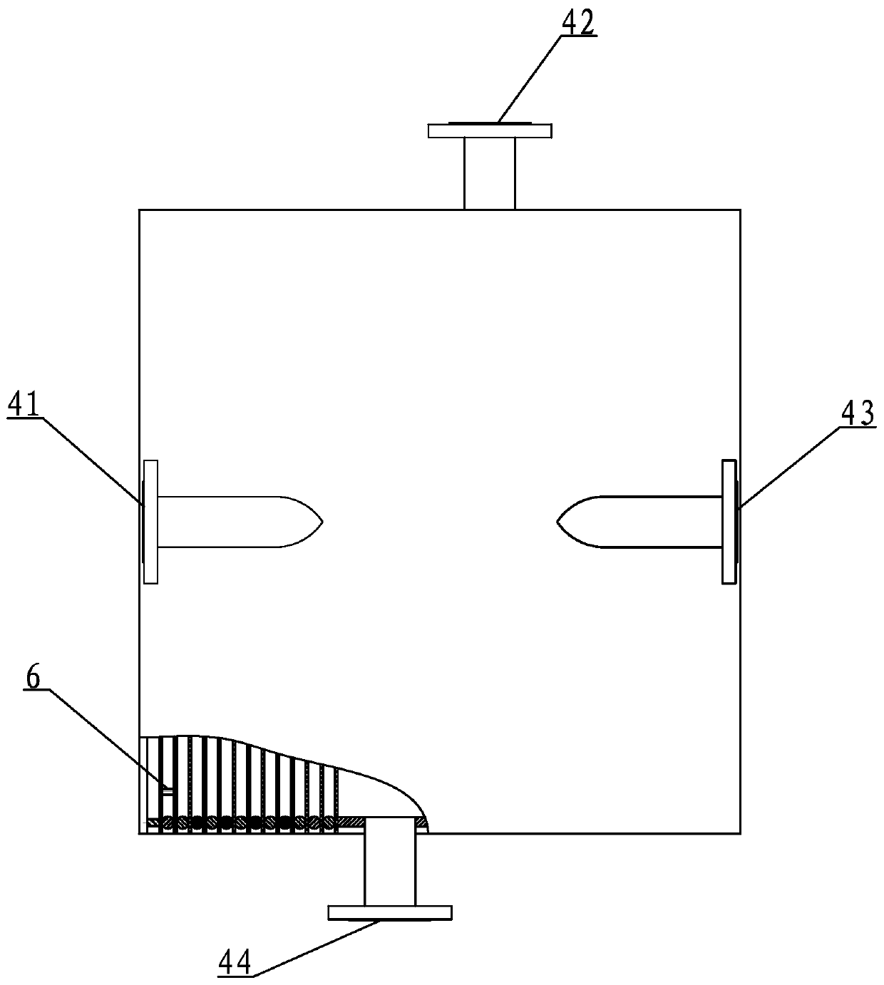
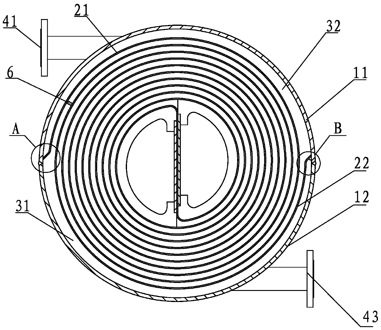
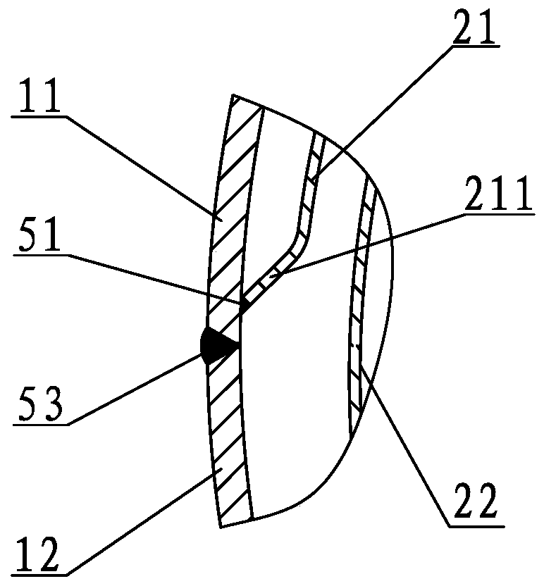

Image

  • A spiral plate heat exchanger and its welding method
  • A spiral plate heat exchanger and its welding method
  • A spiral plate heat exchanger and its welding method

Examples


Embodiment 1

[0026] Embodiment one: see attached figure 1 As shown, a spiral plate heat exchanger includes a cylindrical shell and a heat exchange device arranged in the shell, and the heat exchange device includes first heat exchange plates 21 wound in a helical shape. and the second heat exchange plate 22, and a plurality of spacer columns 6 arranged between the first heat exchange plate 21 and the second heat exchange plate 22, and the housing includes two semicircles welded together barrel-shaped first shell 11 and second shell 12, the outer ends of the first heat exchange plate 21 and the second heat exchange plate 22 are respectively welded to the inner surface of the first shell 11 .

[0027] The first housing 11 includes an arc-shaped body 111 , two arc-shaped arc edge portions 112 located at both ends of the body 111 , and two straight straight edges located at opposite sides of the body 111 . The edge portion 113 , the welded edges of the outer ends of the first heat exchange ...


PUM

PropertyMeasurementUnit
lengthaaaaaaaaaa

Abstract

The invention discloses a spiral board type heat exchanger. The spiral board type heat exchanger comprises a cylindrical shell body and a heat exchange device arranged in the shell body. The heat exchange device comprises a first heat exchange board, a second heat exchange board and a spacing column, wherein the first heat exchange board and the second heat exchange board are spiral and wind mutually, and the spacing column is arranged between the first heat exchange board and the second heat exchange board. The shell body comprises a semi-cylindrical first shell body and a semi-cylindrical second shell body which are welded mutually. The outer ends of the first heat exchange board and the second heat exchange board are welded to the inner surface of the first shell body. Due to the fact that the outer ends of the first heat exchange board and the second heat exchange board are welded to the inner surface of the first shell body, a connecting board adopted in the prior art is omitted, stress can be reduced to a greater degree, and the service life of the heat exchanger is prolonged. Meanwhile, compared with the prior art, the welding method reduces the welded joint filling amount, the labor intensity of a welder is reduced, and the welding cost is saved.

Description

technical field [0001] The invention relates to the field of heat exchangers, in particular to a spiral plate heat exchanger and a welding method thereof. Background technique [0002] The existing spiral plate heat exchanger is rolled by two parallel metal plates to form two independent spiral channels, and two fluids with different temperatures exchange heat through the metal walls. Existing spiral plate heat exchangers are divided into Type I non-detachable type, Type II detachable type and Type III through-type heat exchanger according to the sealing conditions of their passages. At present, no matter what kind of structure it is, the semi-cylindrical body and the spiral plate are welded together through a connecting plate. as attached Figure 6-7 A spiral plate heat exchanger shown includes a first shell 11, a second shell 12, a first heat exchange plate 21, a second heat exchange plate 22, a first connecting plate 71 and a second connecting plate 72, Wherein, one sid...

Claims


Application Information

Patent Timeline
Patent Type & Authority Patents(China)
IPC IPC(8): F28D9/04F28F9/26F28F9/00B23P15/26
CPCB23P15/26F28D9/04F28F9/001F28F9/26F28F2275/06
Inventor 王晓元周家泉
Owner SUZHOU CITY JINXIANG PRESSURE CONTAINER MFG CO LTD
Learn More