
Screw lifting type high-precision board automatic lifting mechanism for PCB separation machine

An automatic lifting and high-precision technology, which is applied in metal processing and other directions, can solve the problems of increasing difficulty, affecting the yield rate, and low efficiency, so as to achieve the effect of easy picking or grabbing, good effect and high efficiency

Active Publication Date: 2017-07-18
浙江蓝天知识产权运营管理有限公司
View PDF6 Cites 1 Cited by
  • Summary
  • Abstract
  • Description
  • Claims
  • Application Information

AI Technical Summary

Problems solved by technology

[0004] The existing PCB sub-boards generally use manual sub-boards, which have poor effect and low efficiency, and manual sub-boards are easy to damage the board and affect the yield, so mechanical sub-boards are now used;
[0005] However, in the existing mechanical sub-boards, the material is generally loaded manually, and it needs to be taken manually from the material box. When the board is at the bottom of the material box, the hand reaching into the bottom of the material box will increase. Difficulty, especially when the board body is close to the ground, it cannot be taken out at all, which is very troublesome and greatly affects the efficiency of feeding

Method used


Image

  • Screw lifting type high-precision board automatic lifting mechanism for PCB separation machine
  • Screw lifting type high-precision board automatic lifting mechanism for PCB separation machine

Examples


Embodiment Construction

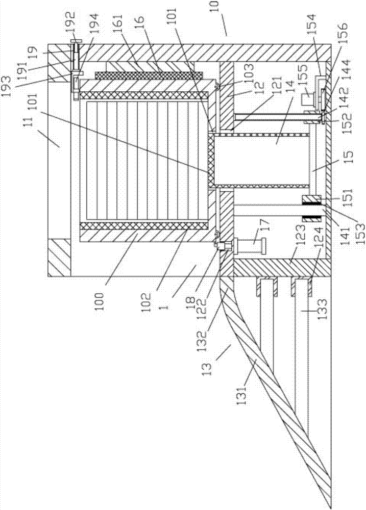
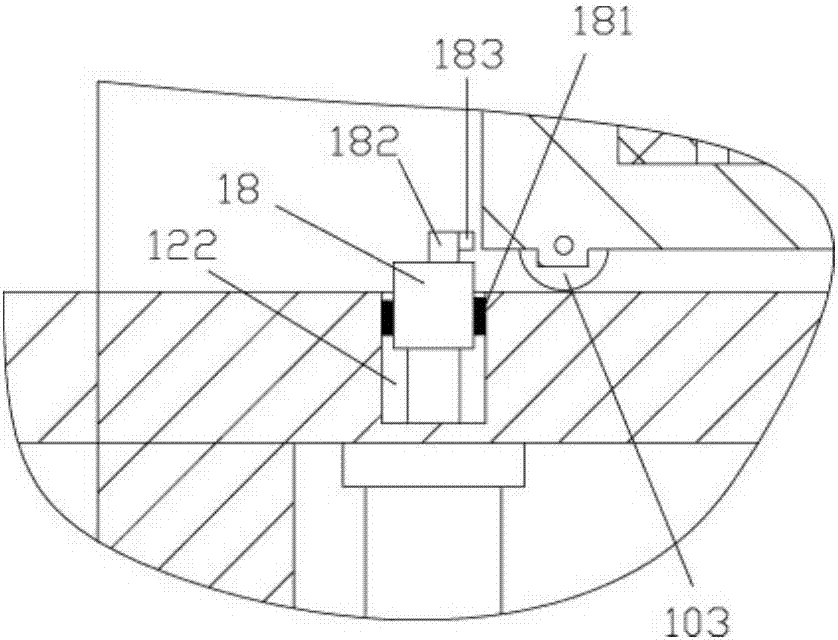
[0026] Examples, see e.g. Figure 1 to Figure 2 As shown, a screw lifting type high-precision plate automatic lifting mechanism for a PCB splitter includes a feeding frame 10, the middle part of the top plate of the feeding frame 10 has a discharge through hole 11, and the middle part of the feeding frame 10 is fixed. There is a support plate 12, the left side of the support plate 12 is provided with a material box conveying inclined frame 13, the left side between the support plate 12 and the top plate of the feeding frame 10 has a material pushing port 1, and the middle part of the support plate 12 has a lifting channel. Hole 121, the push column 14 is inserted in the lifting through hole 121, the bottom end of the push column 14 is below the support plate 12 and is fixed with a lifting connecting plate 15, the left end of the lifting connecting plate 15 is fixed with a guide block 151, and the lifting connecting plate The right-hand member of 15 is fixed with screw joint bl...


PUM


Abstract

The invention discloses a screw lifting type high-precision board automatic lifting mechanism for a PCB separation machine. The screw lifting type high-precision board automatic lifting mechanism comprises a feeding rack. A discharging through hole is formed in the middle portion of a top board of the feeding rack. A supporting board is fixed to the middle portion of the feeding rack. A material box conveying slant frame is arranged on the left side of the supporting board. A material pushing opening is formed in the left side of the position between the supporting board and the top board of the feeding rack. A lifting through hole is formed in the middle portion of the supporting board. A pushing column is inserted into the lifting through hole in a sleeved manner. The bottom end of the pushing column is located below the supporting board and is fixedly provided with a lifting connecting board. A guide block is fixed to the left end of the lifting connecting board. A screw joint block is fixed to the right end of the lifting connecting board. The bottom end of a vertical guide rod is hinged to the left end of a bottom board of the feeding rack. The top end of the vertical guide rod is hinged to the supporting board. The bottom end of an adjusting screw is hinged to the right end of the bottom board of the feeding rack. According to the screw lifting type high-precision board automatic lifting mechanism, a material box can be placed on the supporting board, a material board is automatically lifted through the pushing column, manual or mechanical arm taking or grabbing is facilitated, and the screw lifting type high-precision board automatic lifting mechanism is high in efficiency and good in effect.

Description

[0001] Technical field: [0002] The invention relates to the technical field of circuit board manufacturing and processing, and more specifically relates to a screw lifting type high-precision plate automatic lifting mechanism for a PCB splitting machine. [0003] Background technique: [0004] The existing PCB sub-boards generally use manual sub-boards, which have poor effect and low efficiency, and manual sub-boards are easy to damage the board and affect the yield, so mechanical sub-boards are now used; [0005] However, in the existing mechanical sub-boards, the material is generally loaded manually, and it needs to be taken manually from the material box. When the board is at the bottom of the material box, the hand reaching into the bottom of the material box will increase. Difficulty, especially when the board body is close to the ground, it cannot be taken out at all, which is very troublesome and greatly affects the efficiency of feeding. [0006] Invention content: ...

Claims


Application Information

Patent Timeline
IPC IPC(8): B23Q7/00
CPCB23Q7/005
Inventor 姜硕
Owner 浙江蓝天知识产权运营管理有限公司
Learn More