Device for achieving material forced shrinkage function through differential mechanisms

A technology of differential mechanism and shrinkage function, applied in the field of rubber and plastic machinery, can solve the problems of rubber stacking, rubber material not meeting the process requirements, and affecting product quality, so as to restore the shape, improve the quality of the tread, and avoid stretching Effect

Inactive Publication Date: 2017-07-18
DINGHAN TECH XIAMEN
View PDF0 Cites 1 Cited by
  • Summary
  • Abstract
  • Description
  • Claims
  • Application Information

AI Technical Summary

Problems solved by technology

[0003] In the existing auxiliary line speed chain control method, according to the characteristics of the technological process of tread production, the conveyor roller table between each process section is divided into several sections according to needs. If the speed of the drag motor between the two process sections does not match , it is prone to stretching or stacking, so that the rubber material cannot meet the process requirements
Both of these situations can seriously affect product quality

Method used


Image

  • Device for achieving material forced shrinkage function through differential mechanisms
  • Device for achieving material forced shrinkage function through differential mechanisms
  • Device for achieving material forced shrinkage function through differential mechanisms

Examples


Embodiment Construction

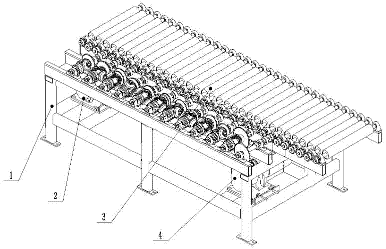
[0023] like figure 1 As shown, a device that uses a differential mechanism to realize the function of forced shrinkage of materials includes a support frame 1, a front frequency conversion motor 2, a roller with a bevel gear differential mechanism 3, and a rear frequency conversion motor 4; the front frequency conversion The motor 1 is installed inside the support frame 2; the rollers 3 with bevel gear differential mechanism are distributed horizontally above the support frame 1; the rear variable frequency motor 4 is fixed under the roller at the right end of the support frame 1; the front variable frequency motor and the rear The variable frequency motors 4 all have even encoders (not shown in the figure).

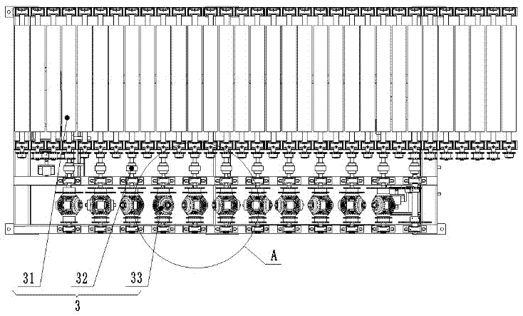
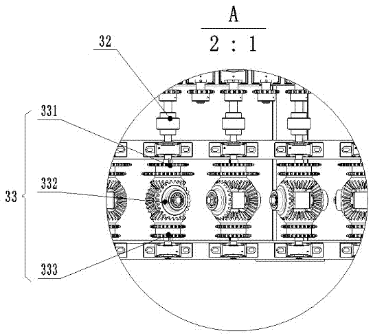
[0024] refer to figure 2 , shows the schematic diagram of the roller 3 with bevel gear differential mechanism of the present invention, the roller with bevel gear differential mechanism, 3 includes transmission roller 31, shaft coupling 32, bevel gear differential mech...


PUM


Abstract

The invention discloses a device for achieving a material forced shrinkage function through differential mechanisms. The device comprises a supporting frame, a front variable frequency motor, rollers with the bevel gear differential mechanisms, and a rear variable frequency motor. The transmission rollers are consistent in diameter, and the tooth number of chain wheels on the bevel gear differential mechanisms connected with the transmission rollers is sequentially and progressively increased from left to right. Under driving of the front variable frequency motor and the rear variable frequency motor which are located at the two ends and have different speeds, the rotation speed of all the transmission rollers is sequentially and progressively changed. Materials are forcibly shrunk on the upper portions of the transmission rollers; the stretching phenomenon is avoided; and the gradual differential speeds are adopted for solving the problem that stretching deformation occurs after tire tread rubber is extruded, so that the shape of the tread rubber is restored. According to the device for achieving the material forced shrinkage function through the differential mechanisms, the structure is simple, adjusting is convenient, and the material quality is greatly improved after the tire rubber surface is extruded.

Description

technical field [0001] The invention also discloses a tread manufacturing control mechanism for the tire industry, especially the control of its shrinkage during tread extrusion, which belongs to the technical field of rubber and plastic machinery. Background technique [0002] The extrusion of tire tread is an important process in the tire manufacturing process, and the shrinkage deformation of tire tread extrusion is directly related to the tire molding quality and production cost. As an indispensable part of a car, tires directly carry the weight of the car. The quality of the tire is one of the main factors affecting the comfort, economy and safety of the car. It can be seen that it is an extremely important task in the automobile industry to ensure that the parameters such as elasticity and size of automobile tires in the production process meet the requirements to ensure the quality of tires. And the production of tire tread is one of the main links in tire production...

Claims


Application Information

Patent Timeline
Patent Type & Authority Applications(China)
IPC IPC(8): B29C47/34B29L30/00B29C48/355
CPCB29C48/355B29L2030/002Y02P70/10
Inventor 沈展王俊彪陈雅娟郑月苹李莉吴艳瑕
Owner DINGHAN TECH XIAMEN
Why Eureka
Try Eureka