Transformer district identification system and transformer district identification method thereof

A technology for identifying systems and station areas, applied in measurement devices, instruments, measuring electricity and other directions, which can solve problems such as high equipment replacement costs

Pending Publication Date: 2017-07-18
CHANGSHA RISECOMM COMM TECH CO LTD
View PDF4 Cites 13 Cited by
  • Summary
  • Abstract
  • Description
  • Claims
  • Application Information

AI Technical Summary

Problems solved by technology

However, in the actual operation of the power grid, there are a large number of narrowband carrier networks and some broadband carrier pilot networks that do not have this function, and the cost of large-scale equipment replacement is huge. Therefore, how to realize station area identification using existing equipment resources has become a research difficulty.

Method used


Image

  • Transformer district identification system and transformer district identification method thereof
  • Transformer district identification system and transformer district identification method thereof
  • Transformer district identification system and transformer district identification method thereof

Examples


Embodiment 1

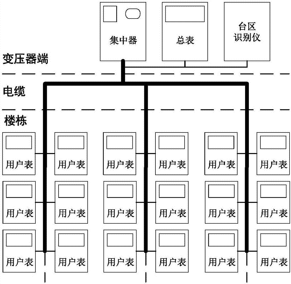
[0023] This embodiment discloses a platform identification system, such as figure 1 As shown, it includes: a concentrator based on carrier communication and a user table, and also includes a station identification device that establishes a communication connection with the concentrator. Usually, one zone corresponds to one zone identifier.

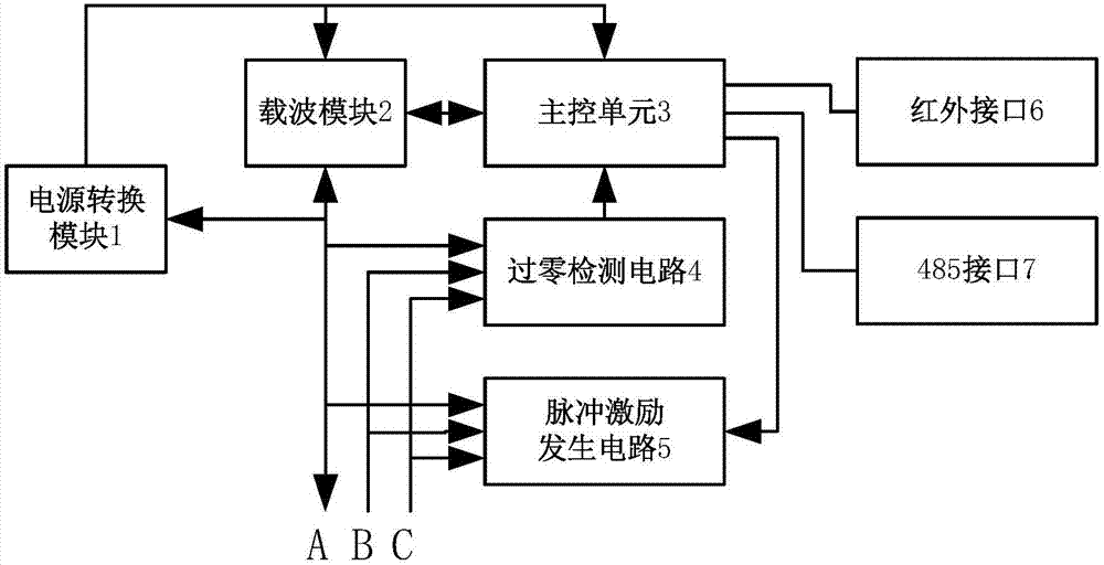
[0024] Such as figure 1 and figure 2 As shown, the station area identification device of this embodiment includes: a power conversion module 1 connected to the single-phase electricity at the transformer end, and its power output terminal is connected with the carrier module 2 and the main control unit 3; the main control chip is also connected with a zero-crossing detection circuit 4 and the pulse excitation generating circuit 5, and the zero-crossing detection circuit and the pulse excitation generating circuit are respectively connected to each phase line.

[0025] Among them, the concentrator is also used to generate the station ar...

Embodiment 2

[0033] Corresponding to the above system, this embodiment discloses a station area identification method, such as Figure 4 shown, including:

[0034] Step S1, the concentrator generates a station area identification command and broadcasts the station area identification command to the station area identification device and the user meter. The station area identification command carries the output mechanism of the pulse excitation signal used to indicate the station area identification device and the response mechanism of the user meter related information.

[0035] Optionally, the station area identification command carries the time and the number of pulses indicating that the station area identification device generates and outputs each phase pulse excitation signal, and the output time of the A, B, and C three-phase pulses generated and output by the station area identification device is as follows: The sequence is staggered. Correspondingly, the user table obtains the co...


PUM


Abstract

The invention relates to the field of intelligent meter reading technology, and discloses a transformer district identification system and a transformer district identification method thereof, thereby realizing transformer district identification by means of an existing equipment resource. The system comprises a concentrator and a user meter based on carrier communication, and a transformer district identification instruction in communication connection with the concentrator. The transformer district identification instrument comprises a power supply conversion module which is connected with single-phase power of a transformer end, wherein the power supply output end of the power supply conversion module is connected with a carrier module and a master control unit. A master control chip is connected with a zero-crossing detecting circuit and a pulse excitation generating circuit. Furthermore the zero-crossing detecting circuit and the pulse excitation generating circuit are respectively with phase wires, so that the master control chip triggers the pulse excitation generating circuit to generate a pulse excitation signal for outputting to a corresponding bus when the zero-crossing detecting circuit detects zero crossing of AC power of a corresponding bus after the master control chip receives a transformer district identification instruction that is broadcast by the concentrator through the carrier module.

Description

technical field [0001] The invention relates to the technical field of intelligent meter reading, in particular to a station area identification system and a method thereof. Background technique [0002] In recent years, in order to achieve refined management of marketing and achieve the goal of reducing consumption and loss, power grid companies often need to collect more user data of various stations, including station information and phase information of user meters, so a proposal for the low-voltage centralized copying system is proposed. new requirements. However, in the actual operation of the power grid, there are a large number of narrowband carrier networks and some broadband carrier pilot networks that do not have this function, and the cost of large-scale equipment replacement is huge. Therefore, how to realize station area identification using existing equipment resources has become a research difficulty. . Contents of the invention [0003] The purpose of th...

Claims


Application Information

Patent Timeline
Patent Type & Authority Applications(China)
IPC IPC(8): G01R31/00
CPCG01R31/00
Inventor 熊凯洲易模刘利方熊海峰
Owner CHANGSHA RISECOMM COMM TECH CO LTD
Why Eureka
Try Eureka