Supercharge Your Innovation With Domain-Expert AI Agents!

Liquid crystal module with fingerprint recognition function

A liquid crystal module and fingerprint recognition technology, which is applied in the field of liquid crystal modules with fingerprint recognition, can solve the problems of fingerprint recognition chip recognition misjudgment, complex manufacturing process, poor yield, difficulty in applying handheld mobile devices, etc., and achieve the goal of improving and improving efficacy Effect

Inactive Publication Date: 2017-07-18
KEYCORE TECH CORP
View PDF5 Cites 0 Cited by
  • Summary
  • Abstract
  • Description
  • Claims
  • Application Information

AI Technical Summary

Problems solved by technology

[0002] The existing liquid crystal display with touch function is mainly to set touch electrodes and lines on the surface side of the liquid crystal display to make the liquid crystal display have the function of touch control. The electrode and wiring structure are arranged on one side of the liquid crystal display in a laminated manner, so that the liquid crystal display has the function of fingerprint recognition. Although this design can achieve the functions of touch and fingerprint recognition required by users, it is currently At this stage, hand-held mobile devices are developing toward thinning. Therefore, if the fingerprint identification structure and electrodes and the touch structure and electrodes are respectively arranged on the liquid crystal display layer by layer using the stacking method, it will not be able to meet the thinning requirements. Moreover, the fingerprint identification Image input can be divided into optical scanning, thermal image sensing, capacitive sensing, etc.
Due to the large size of the device, the consideration of power consumption or the complexity of the manufacturing process, the yield rate is not good, and it is generally easy to be deceived by fake fingerprints, which makes it difficult to apply to handheld mobile devices, and the accuracy and reliability of thermal image sensing are not good. Therefore, capacitive image sensing has gradually become the mainstream technology for biometric identification in mobile electronic devices
[0003] However, the distance between the fingerprint identification chip and the surface glass is also an important design point. When the distance between the fingerprint identification chip and the surface where the fingerprint is detected is too far, it is easy to cause misjudgment by the fingerprint identification chip. Therefore, the existing fingerprint identification structure Can only be set on the surface of the LCD display

Method used


Image

  • Liquid crystal module with fingerprint recognition function
  • Liquid crystal module with fingerprint recognition function
  • Liquid crystal module with fingerprint recognition function

Examples


Embodiment Construction

[0063] The above-mentioned objects of the present invention and the structural and functional characteristics of the present invention will be described based on the preferred embodiments of the drawings.

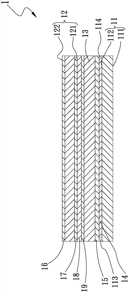
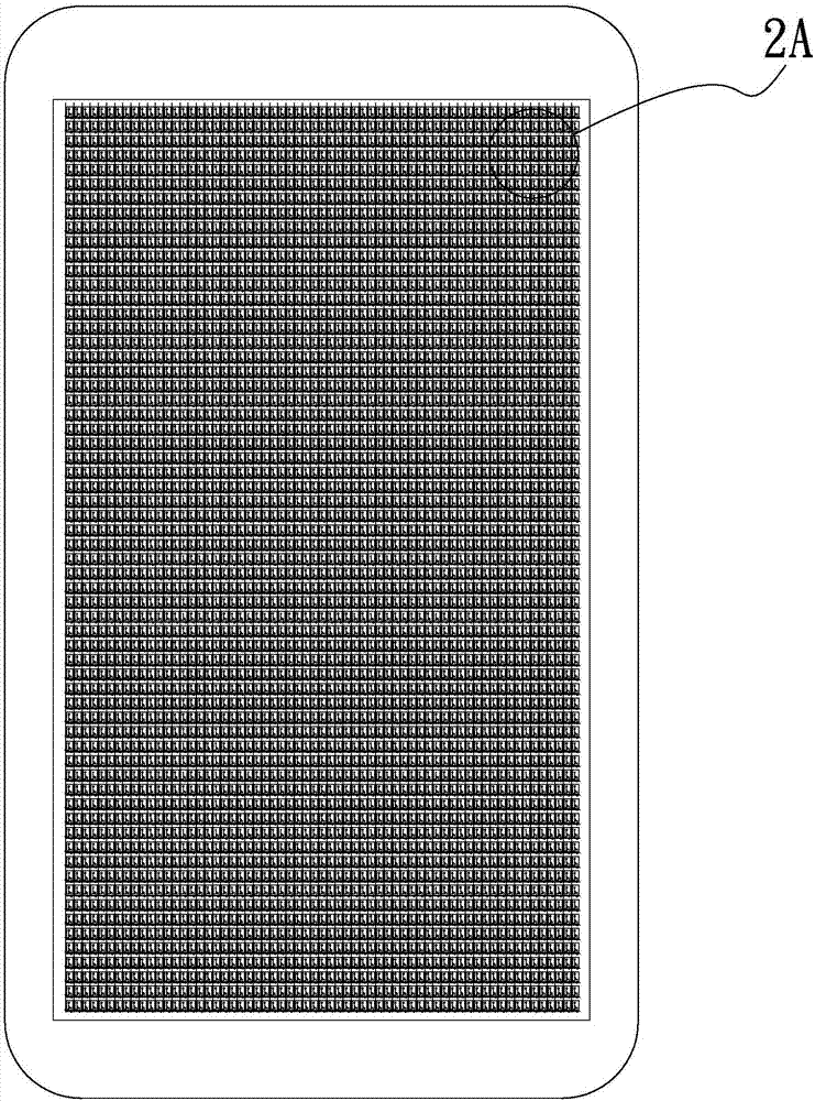
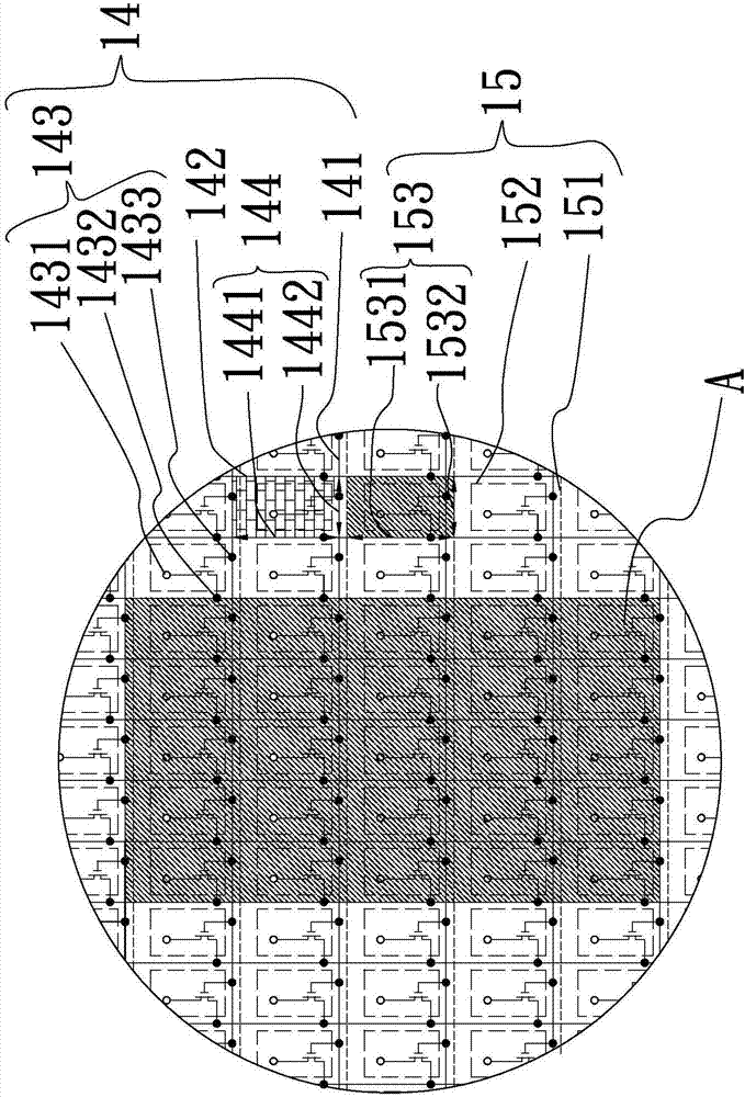
[0064] See figure 1 , figure 2 , Figure 2A and Figure 2B , Is the combined cross-sectional and top view of the first embodiment of the liquid crystal module with fingerprint recognition of the present invention. As shown in the figure, the liquid crystal module 1 with fingerprint recognition includes: an array of glass substrates 11 and a color filter glass Substrate 12, a liquid crystal material layer 13, a pixel display layer 14, a detection wiring and sensing electrode layer 15, a first chip 113, and a second chip 114;

[0065] The array of glass substrates 11 has a first side surface 111 and a second side surface 112, and the first side surface 111 and the second side surface 112 are oppositely disposed on the upper and lower sides of the array glass substrate 11.

[0066] ...


PUM


Abstract

A liquid crystal module with a fingerprint recognition function comprises an array glass substrate, a color filter glass substrate, a liquid crystal material layer, a pixel display layer and a detection wire and sensing electrode layer, wherein the liquid crystal material layer, the pixel display layer and the detection wire and sensing electrode layer are arranged between the array glass substrate and the color filter glass substrate. The liquid crystal module mainly realizes combined functions of display, fingerprint recognition and touch control through mutual cooperation of the pixel display layer and internal wire and electrode structures of the detection wire and sensing electrode layer.

Description

Technical field [0001] A liquid crystal module with fingerprint recognition, especially refers to a liquid crystal module with fingerprint recognition and touch functions. Background technique [0002] The existing liquid crystal display with touch function mainly has touch electrodes and lines on the surface side of the liquid crystal display to make the liquid crystal display have the touch function. If the same is required to have a fingerprint recognition function, the fingerprint recognition function is additionally required. The electrodes and wiring structure are arranged on the side of the liquid crystal display in a laminated manner, so that the liquid crystal display has the function of fingerprint recognition. Although this design can achieve the touch and fingerprint recognition functions required by the user, it is now Hand-held mobile devices are becoming thinner. Therefore, if the fingerprint recognition structure and the electrode and the touch structure and the e...

Claims


Application Information

Patent Timeline
Patent Type & Authority Applications(China)
IPC IPC(8): G02F1/1343G02F1/1333G02F1/1362G06K9/00
CPCG02F1/13338G02F1/134309G02F1/136286G06V40/1306
Inventor 林韦丞萧建仁曾士修
Owner KEYCORE TECH CORP
Features
  • R&D
  • Intellectual Property
  • Life Sciences
  • Materials
  • Tech Scout
  • Unparalleled Data Quality
  • Higher Quality Content
  • 60% Fewer Hallucinations
Learn More