

Method of realizing uplink power control and terminal
A power control and terminal technology, applied in power management, wireless communication, electrical components, etc., can solve the problem that the uplink power control scheme has not yet been designed
- Summary
- Abstract
- Description
- Claims
- Application Information
AI Technical Summary
Problems solved by technology
Method used
Image

Examples
application example 1
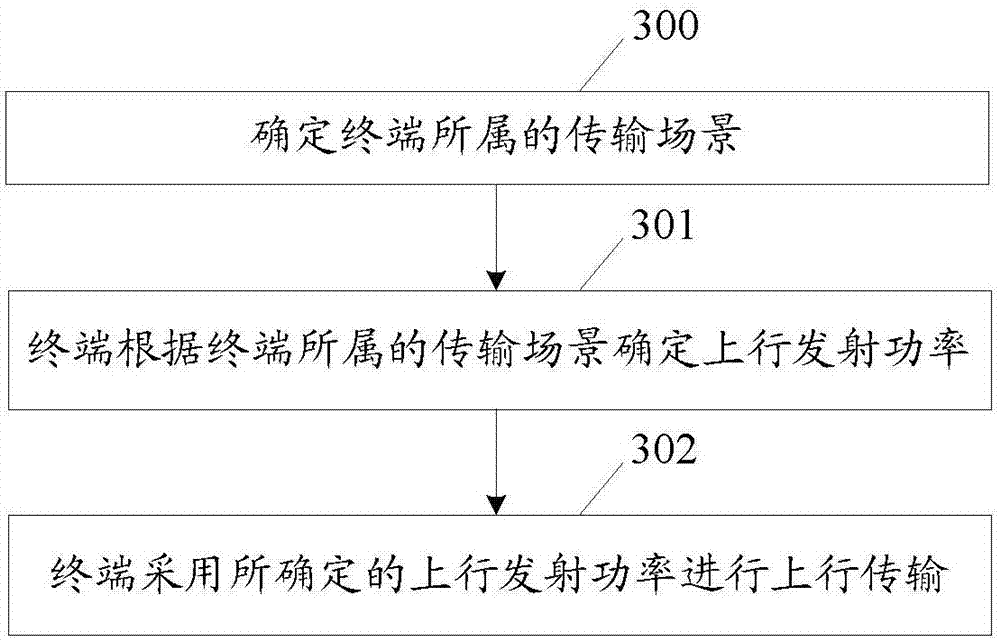
[0284] The method flowchart of application example 1 of the present invention is as follows image 3 shown, including:
[0285] Step 300, determine the transmission scenario to which the terminal belongs;
[0286] The terminal determines the transmission scenario to which the terminal belongs according to one or more of factors such as transmission capability or mode, number of subcarriers, coverage level, channel type, and information to be sent, among which:
[0287] The transmission capability or mode includes: single-carrier single tone transmission, the carrier bandwidth is the first bandwidth; single-carrier single tone transmission, the carrier bandwidth is the second bandwidth; multi-carrier Multi-tone transmission, the carrier bandwidth is the third bandwidth; multi-carrier Multi- tone transmission, the carrier bandwidth is the fourth bandwidth; wherein, the first bandwidth is different from the second bandwidth, for example: the first bandwidth can be 3.75kHz, the s...
application example 2
[0298] Examples of applications of the invention include:
[0299] First, determine the transmission scenario to which the terminal belongs;
[0300] The terminal determines the transmission scenario to which the terminal belongs according to one or more of factors such as transmission capability or mode, number of subcarriers, coverage level, channel type, and information to be sent, as described in application example 1.
[0301] In this application example, for example, according to its transmission capability or mode configuration information, the terminal determines that it supports multi-carrier multi-tone transmission with a carrier bandwidth of the fourth bandwidth (for example, 15kHz), and determines that its coverage level is coverage level 1 according to the downlink measurement results. And the random access Preamble will be sent by using multi-carrier multi-tone through NB-PRACH, then the terminal can determine the transmission scenario it belongs to according to ...
application example 3
[0318] Application example 3 of the present invention includes:
[0319] First, determine the transmission scenario to which the terminal belongs;
[0320] The terminal determines the transmission scenario to which the terminal belongs according to one or more of factors such as transmission capability or mode, number of subcarriers, coverage level, channel type, and information to be sent, as described in application example 1.
[0321] In this application example, for example, according to its transmission capability or mode configuration information, the terminal determines that it supports multi-carrier multi-tone transmission with a carrier bandwidth of the fourth bandwidth (for example, 15kHz), and determines that its coverage level is coverage level 1 according to the downlink measurement results. And the uplink control information will be sent through the NB-PUSCH using a single-carrier single tone, then the terminal can determine the transmission scenario it belongs t...
PUM
 Abstract
Description
Claims
Application Information