Clamping device for camshaft machining

A clamping device and camshaft technology, applied in positioning devices, metal processing equipment, metal processing machinery parts, etc., can solve the problems of low clamping efficiency, achieve good clamping effect, improve efficiency, and shorten the use of clamping the effect of time

Active Publication Date: 2017-07-21
南通利联机床制造有限公司
View PDF7 Cites 8 Cited by
  • Summary
  • Abstract
  • Description
  • Claims
  • Application Information

AI Technical Summary

Problems solved by technology

[0007] The present invention intends to provide a clamping device for camshaft processing to solve the problem of low clamping efficiency in the prior art

Method used


Image

  • Clamping device for camshaft machining
  • Clamping device for camshaft machining

Examples


Embodiment Construction

[0023] The present invention will be described in further detail below by means of specific embodiments:

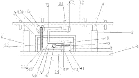
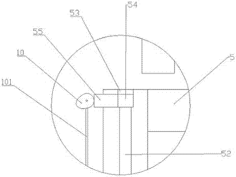
[0024] The reference signs in the accompanying drawings of the description include: base 1, first support column 2, second support column 3, U-shaped connector 4, first horizontal tube 41, first piston 411, second horizontal tube 42, second Piston 421, vertical pipe 43, limit rod 44, positioning column 5, first horizontal push rod 51, air hole 511, through hole 52, installation groove 53, bump 54, positioning block 55, locking column 6, second horizontal Push rod 61, clamping block 62, gear 7, rack 8, support frame 9, cam 10, bracket 101, height adjustment block 11, camshaft 12, protruding ring 121.

[0025] Such as figure 1 As shown, the clamping device for cam 10 shaft processing includes a base 1, on which a first support column 2, a U-shaped connector 4 with an opening facing left, a second support column 3, and a first support column 3 are arranged on the base 1 fro...


PUM


Abstract

The invention belongs to the technical field of machining and discloses a clamping device for camshaft machining. The clamping device comprises a base. The base is provided with a first supporting column, a U-shaped communicating vessel and a second supporting column. The U-shaped comprises a first transverse pipe, a second transverse pipe and a vertical pipe. The clamping device further comprises an L-shaped positioning column and a locking column. The lower end of a long pole of the positioning column is connected with a first transverse push rod. The lower end of the long pole of the locking column is connected with a second transverse push rod. The right end of the first transverse push rod is connected with a first piston. The right end of the second transverse push rod is connected with a second piston. A gear is arranged between the first transverse push rod and the second transverse push rod. The first transverse push rod and the second transverse push rod are both provided with racks. Air holes are formed in the first transverse push rod. Through holes are formed in the long pole of the positioning column. A mounting groove is formed in the top end of the long pole of the positioning column. A transverse protrusion block and a vertical positioning block are arranged in the mounting groove. A rotary shaft is arranged on the left side of the positioning block. A cam and a torsional spring are connected to the rotary shaft. The problem that the clamping efficiency in the prior art is low is solved.

Description

technical field [0001] The invention belongs to the field of mechanical processing, and in particular relates to a clamping device for camshaft processing. Background technique [0002] The camshaft is a part in the piston engine, which is used to control the opening and closing of the valve. It includes a main shaft and several protruding rings on the outer ring of the main shaft, and the circular parts of adjacent protruding rings are all staggered. In the process of camshaft processing, the two ends are usually fixed. After the processing is completed, the center hole is drilled as a positioning reference, and then the two ends are processed. This method requires multiple steps for processing and consumes a lot of equipment. It takes a lot of clamping time, and the processing efficiency is low. [0003] Therefore, in order to solve the above-mentioned technical problems, the Chinese patent whose patent publication number is CN103949922B provides a kind of fast positionin...

Claims


Application Information

Patent Timeline
Patent Type & Authority Applications(China)
IPC IPC(8): B23Q3/06
CPCB23Q3/062
Inventor 刘长
Owner 南通利联机床制造有限公司
Why Eureka
Try Eureka