Gripping mechanism for waste filtering core replacement and transfer unit device

A technology of unit device and grasping mechanism, applied in the directions of transportation and packaging, conveyor objects, etc., can solve problems such as being susceptible to radiation, and achieve the effect of improving safety and improving safety level

Active Publication Date: 2017-07-21
DALIAN CLEAN ENERGY HEAVY IND
View PDF8 Cites 3 Cited by
  • Summary
  • Abstract
  • Description
  • Claims
  • Application Information

AI Technical Summary

Problems solved by technology

[0003] Aiming at the above-mentioned problems existing in the prior art, this application provides a grasping mechanism that can be used in nuclear power plant waste filter element replacement transfer unit device, which solves the problem that the shielding cover of the existing filter element room needs to be manually opened and is easily exposed to radiation

Method used


Image

  • Gripping mechanism for waste filtering core replacement and transfer unit device
  • Gripping mechanism for waste filtering core replacement and transfer unit device
  • Gripping mechanism for waste filtering core replacement and transfer unit device

Examples


Embodiment 1

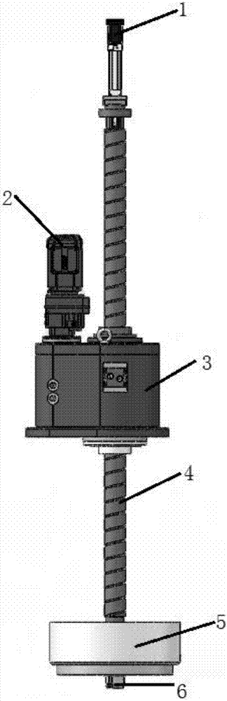
[0024] This embodiment provides a grasping mechanism for a waste filter element replacement transfer unit device, including: a grasper electric cylinder, a reduction motor, a transmission gearbox, a lead screw, a sealing ring, and a grasper claw; the lead screw passes through the transmission gear There is a gripper electric cylinder on the top of the lead screw, and a sealing ring at the bottom. The gripper claw is placed under the sealing ring, and the deceleration motor is installed on the transmission gear box, which can remotely control the movement of the lead screw Lifting, the transmission gearbox is fixed on the waste filter element replacement transfer unit device.

[0025] Preferably, the transmission gearbox is provided with a transmission mechanism overload protector and a safety nut; the transmission mechanism overload protector prevents the reduction motor from being overloaded and fails, and the safety nut prevents the lead screw from falling due to long-term we...

Embodiment 2

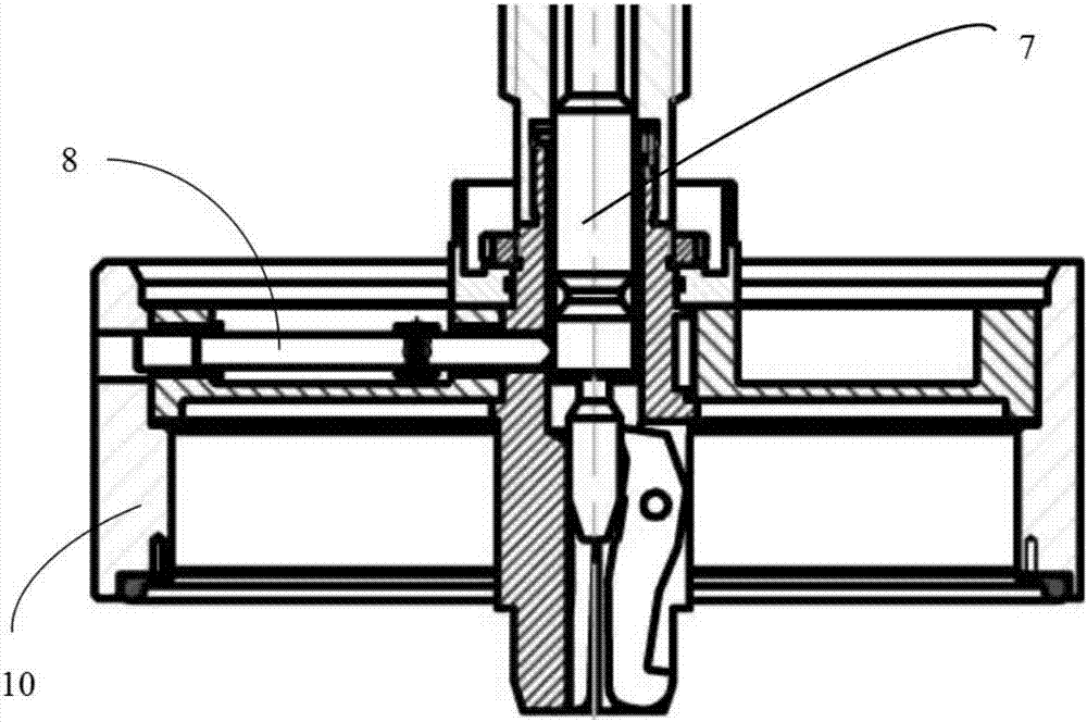
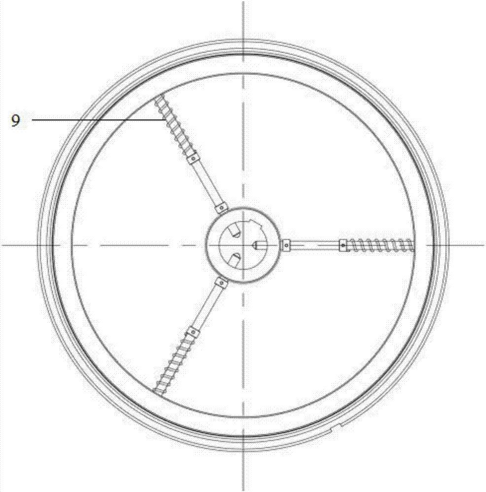
[0027] As a further supplement to Embodiment 1, the application provides a sealing ring, including a sealing disc and a shielding container ring, and the shielding container ring is respectively connected with the waste filter element replacement transfer unit device and the filter element chamber to play a sealing role; the sealing disc There is a pin hole on the side, and the pin rod is fixed by a compression spring. One end is against the connecting rod inside the lead screw, and the other end passes through the pin hole to block the shielding container ring. The electric cylinder of the gripper is connected to one end of the connecting rod inside the lead screw. The other end of the connecting rod is against the claw of the gripper and has a V-groove matching the size of the pin rod. The shielding container ring falls automatically when the claws of the gripper grab the lid of the shielding container, and is automatically retracted when the claws of the gripper break away f...


PUM


Abstract

The invention discloses a gripping mechanism for a waste filtering core replacement and transfer unit device. The gripping mechanism comprises a gripper electric cylinder, a gear motor, a transmission gear box, a screw rod, a sealing ring and a gripper lifting claw. The screw rod penetrates through the transmission gear box. The gripper electric cylinder is arranged at the top of the screw rod, and the sealing ring is arranged at the bottom of the screw rod. The gripper lifting claw is arranged under the sealing ring. The gear motor is installed on the transmission gear box. The transmission gear box is fixed to the waste filtering core replacement and transfer unit device. According to the gripping mechanism for the waste filtering core replacement and transfer unit device, gripping or releasing of a shielding container cover can be conducted under the sealed condition through remote control and does not need to be operated by personnel in a close mode, so that radiation to the personnel is avoided, and the safety grade of nuclear power equipment in the replacement process is greatly improved.

Description

technical field [0001] The invention relates to a grasping mechanism, in particular to a grasping mechanism of a waste filter element replacement transfer unit device. Background technique [0002] At present, in the radioactive water treatment system of domestic nuclear power plants, a large number of water filters with different sizes and specifications and different filtration accuracy requirements are used. When the pressure difference or radioactive level of the filter element of the used filter reaches the set value, the filter element will be replaced and discarded. The filter element is radioactive, so it needs to be reconditioned to meet the needs of environmental safety. The filter element is placed in the filter element chamber which has the effect of shielding radiation. In order to be able to grasp and replace the filter element, currently domestic personnel use equipment and tools to manually open the shielding cover of the filter element chamber to grab the f...

Claims


Application Information

Patent Timeline
Patent Type & Authority Applications(China)
IPC IPC(8): B65G47/90
CPCB65G47/901
Inventor 王成伟王宁尹忠阳童欣李万垚赵莉霞朱洪秀
Owner DALIAN CLEAN ENERGY HEAVY IND
Why Eureka
Try Eureka