Carrying-transformer device for substation

A technology for handling devices and transformers, which is applied to transformer handling devices, transformer/inductor components, circuits, etc., can solve the problems of cumbersome operation, labor-intensive labor, and slow handling speed.

Active Publication Date: 2017-07-21
中国电建集团河北工程有限公司
View PDF11 Cites 4 Cited by
  • Summary
  • Abstract
  • Description
  • Claims
  • Application Information

AI Technical Summary

Problems solved by technology

[0006] In order to overcome the shortcomings of manual handling, the labor intensity of workers is high, the handling speed is slow, and the existing handling device is cumbersome, the technical problem to be

Method used


Image

  • Carrying-transformer device for substation
  • Carrying-transformer device for substation
  • Carrying-transformer device for substation

Examples


Embodiment 1

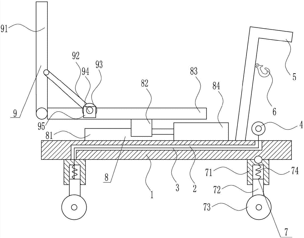
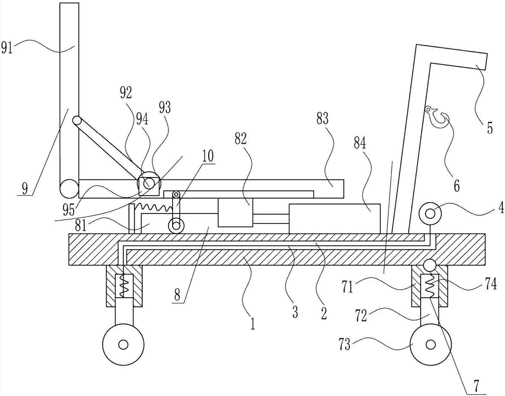
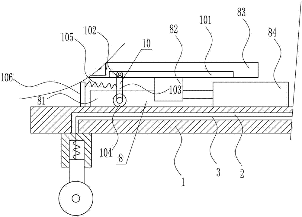
[0029] A transformer handling device for a substation, such as Figure 1-4 As shown, it includes a mounting plate 1, a pull wire 3, a pull ring 4, a push rod 5, an arc-shaped fixed rod 6, a shock absorbing device 7, a left and right moving device 8 and a fixing device 9, and the mounting plate 1 is provided with a through hole 2, The through hole 2 is provided with a stay wire 3, the top of the stay wire 3 passes through the top right side of the installation plate 1, the top of the stay wire 3 is connected to the pull ring 4 through a hook, the tail end of the stay wire 3 passes through the left bottom of the installation board 1, and the bottom of the installation board 1 The left and right sides of the bottom are provided with a shock absorber 7, the right shock absorber 7 is connected with the right side of the bottom of the mounting plate 1 by a pin, the tail end of the pull wire 3 is connected with the left shock absorber 7 through a hook, and the right side of the mounti...

Embodiment 2

[0031] A transformer handling device for a substation, such as Figure 1-4 As shown, it includes a mounting plate 1, a pull wire 3, a pull ring 4, a push rod 5, an arc-shaped fixed rod 6, a shock absorbing device 7, a left and right moving device 8 and a fixing device 9, and the mounting plate 1 is provided with a through hole 2, The through hole 2 is provided with a stay wire 3, the top of the stay wire 3 passes through the top right side of the installation plate 1, the top of the stay wire 3 is connected to the pull ring 4 through a hook, the tail end of the stay wire 3 passes through the left bottom of the installation board 1, and the bottom of the installation board 1 The left and right sides of the bottom are provided with a shock absorber 7, the right shock absorber 7 is connected with the right side of the bottom of the mounting plate 1 by a pin, the tail end of the pull wire 3 is connected with the left shock absorber 7 through a hook, and the right side of the mounti...

Embodiment 3

[0034] A transformer handling device for a substation, such as Figure 1-4 As shown, it includes a mounting plate 1, a pull wire 3, a pull ring 4, a push rod 5, an arc-shaped fixed rod 6, a shock absorbing device 7, a left and right moving device 8 and a fixing device 9, and the mounting plate 1 is provided with a through hole 2, The through hole 2 is provided with a stay wire 3, the top of the stay wire 3 passes through the top right side of the installation plate 1, the top of the stay wire 3 is connected to the pull ring 4 through a hook, the tail end of the stay wire 3 passes through the left bottom of the installation board 1, and the bottom of the installation board 1 The left and right sides of the bottom are provided with a shock absorber 7, the right shock absorber 7 is connected with the right side of the bottom of the mounting plate 1 by a pin, the tail end of the pull wire 3 is connected with the left shock absorber 7 through a hook, and the right side of the mounti...


PUM


Abstract

The invention relates to a carrying-transformer device, in particular to the carrying-transformer device for a substation. The technical problem to be solved is how to provide the carrying-transformer device for the substation, which can reduce the labor intensity of workers to improve the carrying speed and render operations simple and use convenient. According to the technical scheme to solve the above technical problems, the carrying-transformer device for the substation comprises a mounting plate, a pull wire, a pull ring, a push rod, an arc fixing rod, a shock-absorbing device and the like. The mounting plate is provided with a through hole which is internally provided with the pull wire. The top end of the pull wire passes through the right top of the mounting plate and is connected with the pull ring through a hook, and the tail end of the pull wire passes through the left bottom of the mounting plate. The shock-absorbing device of the carrying-transformer device can play a shock absorption effect on the transformer in the moving process, therefore the carrying-transformer device has the advantages of reducing the labor intensity of workers, improving the carrying efficiency, and being simple in operation and convenient to use.

Description

technical field [0001] The invention relates to a transformer handling device, in particular to a transformer handling device for a substation. Background technique [0002] Substation, a place where voltage is changed. In order to transmit the electric energy from the power plant to a distant place, the voltage must be raised to become high-voltage electricity, and then the voltage is lowered as needed near the user. This work of raising and lowering the voltage is done by the substation. The main equipment of substations are switches and transformers. According to the size, the small ones are called substations. A substation is larger than a substation. A substation is a power facility in the power system that transforms voltage, receives and distributes electric energy, controls the flow of power, and adjusts voltage. It connects the power grids of all levels of voltage through its transformers. [0003] The transformer is a device that uses the principle of electroma...

Claims


Application Information

Patent Timeline
IPC IPC(8): H01F27/00
CPCH01F27/002
Inventor 王志强
Owner 中国电建集团河北工程有限公司
Why Eureka
Try Eureka