A Bearing Oiling Alignment Machine

An alignment machine and oiling technology, which is applied in the direction of coating, surface coating liquid device, etc., can solve the problem of low oiling efficiency and achieve the effect of high uniformity, good antirust performance and high efficiency

Active Publication Date: 2019-02-15
浙江万通轴承股份有限公司
View PDF1 Cites 3 Cited by
  • Summary
  • Abstract
  • Description
  • Claims
  • Application Information

AI Technical Summary

Problems solved by technology

[0003] In order to evenly oil the rolling bearings, the traditional bearing manufacturers usually set a sponge layer on the flat table, and spread the bearings to be oiled on the sponge layer in turn, and then use a cloth with anti-rust oil to clean them one by one. Each flat bearing is oiled, and after one side is oiled, each bearing needs to be turned over and oiled again; the work efficiency of oiling is extremely low

Method used


Image

  • A Bearing Oiling Alignment Machine
  • A Bearing Oiling Alignment Machine
  • A Bearing Oiling Alignment Machine

Examples


Embodiment 1

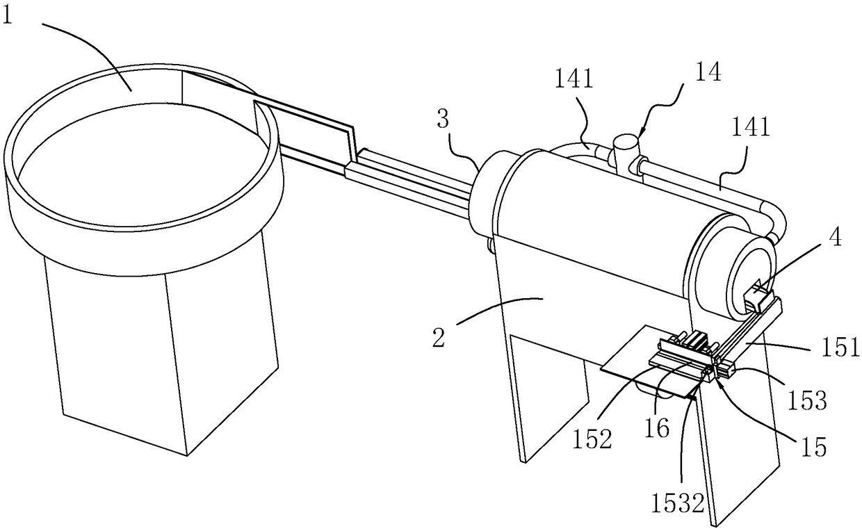
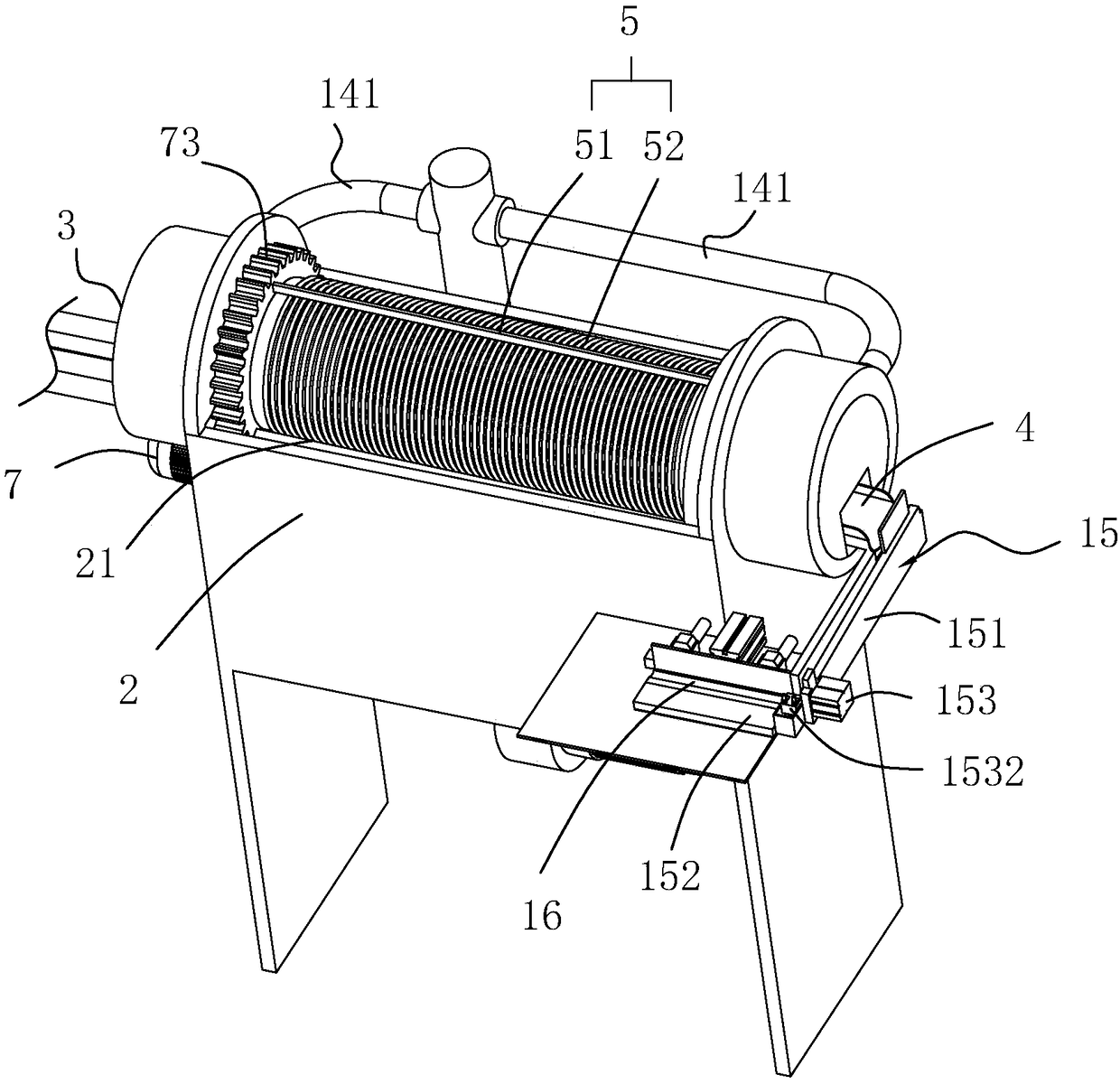
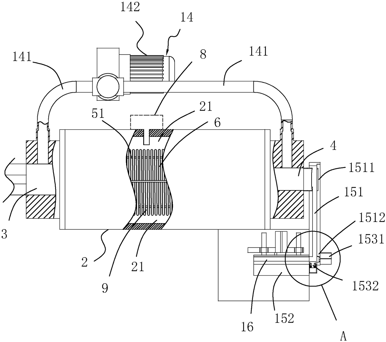
[0038] A bearing oiling alignment machine, see figure 1 , figure 2 as well as image 3 As shown, it includes a feeding mechanism 1, a machine body 2, and a feeding mechanism 15 respectively arranged from left to right, wherein the feeding mechanism 1 can choose a vibrating feeding tray structure, and the body 2 is provided with a feeding channel in turn from left to right 3. The oiling chamber 21, the discharge channel 4, the feeding mechanism 1 is connected to the oiling chamber 21 through the feeding channel 3, and the oiling chamber 21 is provided with an oiling cylinder 5, a driving part 7, an atomizing spray Oil part 8, the two ends of the oiling cylinder 5 are respectively connected with the feed passage 3 and the discharge passage 4, and several gap passages 9 are arranged on the outer cylinder wall of the oiling cylinder 5, and the oiling cylinder 5 One end close to the feed channel 3 is inclined toward the end of the oiling cylinder 5 close to the discharge channel...

Embodiment 2

[0044] Embodiment 2: The difference from Embodiment 1 is that, see Figure 5 As shown, the oiling frame 52 includes a helical spring-shaped oiling member 6, and the driving portion 7 includes a driving motor 71, which is installed on the body 2, and the driving end of the driving motor 71 extends into the coating of the body 2. In the oil chamber 21 and the driving end is connected with a driving gear 72, and the oiling cylinder part 5 is also fixedly provided with a driven toothed plate 73, and in the oiling chamber 21, two supporting frames 10 are vertically arranged, and the two supporting frames The upper end of the frame 10 is directly supported against the outer peripheral side wall of the paint cylinder; when the drive motor 71 is started, the drive gear 72 is engaged with the driven toothed disc 73, and the entire oil paint cylinder 5 can be rotated circumferentially.

[0045] see Figure 6 as well as Figure 7 As shown, several locking pieces 11 are also arranged on...


PUM


Abstract

The invention discloses a bearing oiling orderly arranging machine. According to the technical scheme, the bearing oiling orderly arranging machine is characterized by comprising a feeding mechanism, a discharging mechanism and a machine body; the machine body is internally provided with an oiling cavity, a feeding channel and a discharging channel; the oiling cavity is internally provided with an oiling barrel, a driving part and an atomization oil injection part; one end of the oiling barrel is connected with the feeding channel, and the other end of the oiling barrel is connected with the discharging channel; the oiling barrel is obliquely arranged overall and is provided with a plurality of clearance channels; the atomization oil injection part is used for conducting atomization oil injection on the oiling barrel; the feeding mechanism is located on one side of the feeding channel of the machine body and used for transporting to-be-oiled bearings to the feeding channel; and the discharging mechanism is located on one side of the discharging channel of the machine body and used for orderly arranging the oiled bearings. According to the bearing oiling orderly arranging machine, automatic oiling is conducted in the whole action process, not only is the oiling efficiency very high, but also the oiling uniformity is very high, the large-batch bearing oiling requirements can be met, and the bearings oiled through the oiling orderly arranging machine is good in antirust property.

Description

technical field [0001] The invention relates to a bearing oiling device, in particular to a bearing oiling alignment machine. Background technique [0002] Deep groove ball bearing is the most common type of rolling bearing. Its structure is as shown in the Chinese invention whose notification number is CN202937623U. It includes an outer ring and an inner ring, and a steel ball group is arranged between the outer ring and the inner ring; the outer ring Rotating relative to the inner ring, the steel ball group can greatly reduce the friction between the inner ring and the outer ring. In order to ensure the rolling stability of the outer ring and the inner ring, a cage is also set in the deep groove ball bearing , to maintain the distance between the steel balls in the outer ring and inner ring; after the production of deep groove ball bearings of this type of structure is completed, it is necessary to apply corresponding anti-rust oil to the outer side of the bearing to ensur...

Claims


Application Information

Patent Timeline
Patent Type & Authority Patents(China)
IPC IPC(8): B05C5/02B05C13/02B05C11/10
CPCB05C5/02B05C11/10B05C11/1039B05C13/025
Inventor 王涛赵加兵
Owner 浙江万通轴承股份有限公司
Why Eureka
Try Eureka