A milling tool with self-pressing function

A milling tool and self-compression technology, applied in the field of metal cutting processing, can solve the problems of uncontrolled initial height difference range, increase the difficulty of tool body manufacturing, and uncertain blade position, so as to save adjustment time and simplify adjustment. Structure and steps of adjusting the tool, the effect of height difference reduction

Active Publication Date: 2018-11-06
ZHUZHOU CEMENTED CARBIDE CUTTING TOOLS CO LTD
View PDF8 Cites 0 Cited by
  • Summary
  • Abstract
  • Description
  • Claims
  • Application Information

AI Technical Summary

Problems solved by technology

[0007] 2) Due to the existence of the adjusting wedge, the pressing wedge and its double-headed screw, the cutter body groove also needs to be provided with a corresponding pressing groove and threaded hole, which increases the difficulty of manufacturing the cutter body;
[0008] 3) There are many steps in the process of adjusting the tool, and it takes a long time to adjust the tool;
[0009] 4) The initial position of the adjustment wedge is uncertain, so the position of the inclined surface is uncertain, and the position of the blade in contact with it is also uncertain. The range of the initial height difference between each blade is not controlled. When the value is large, the adjustment time is prolonged

Method used


Image

  • A milling tool with self-pressing function
  • A milling tool with self-pressing function
  • A milling tool with self-pressing function

Examples


Embodiment Construction

[0040] The present invention will be described in further detail below in conjunction with the accompanying drawings and specific embodiments.

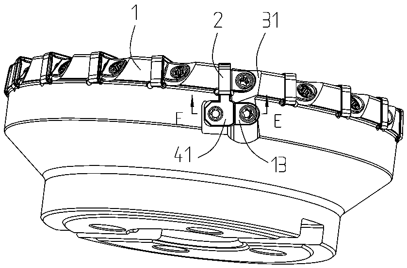
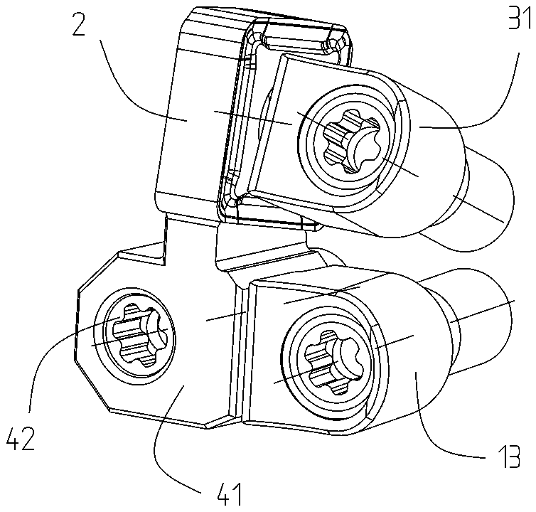
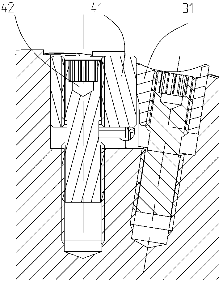
[0041] Figure 4 to Figure 11An embodiment of the milling tool with self-compressing function of the present invention is shown. The milling tool with self-compressing function includes a cutter body 1, a cutting blade 2, a pressing assembly 3 and a blade position adjustment assembly 4. The body 1 is provided with a blade groove 11 and an adjusting wedge groove 14, the cutting blade 2 is installed in the blade groove 11 through the pressing assembly 3, and the blade position adjusting assembly 4 includes an adjusting wedge 41 and a device that can drive the adjusting wedge 41 to move. Drive the screw 42, the adjustment wedge 41 is located in the adjustment wedge groove 14, the adjustment wedge 41 includes a wedge top 412, a wedge bottom 413, a wedge left 414, a wedge right 415, a wedge front 416 and a wedge back 417, the wedge top su...


PUM


Abstract

The invention provides a milling tool with a self-compacting function. A blade position adjusting assembly comprises an adjusting wedge block and a drive bolt. The adjusting wedge block is located in an adjusting wedge block groove. The adjusting wedge block comprises a wedge block top face, a wedge block bottom face, a wedge block left face, a wedge block right face, a wedge block front face and a wedge block rear face. The wedge block top face is a wedge face. An acute angle alpha is formed between the wedge block right face and the wedge block bottom face. A strip-shaped groove is formed in the wedge block rear face. The groove penetrates the wedge block top face and the wedge block bottom face. The wedge block right face is provided with a first inclined face. An acute angle beta is formed between the first inclined face and the wedge block left face. The adjusting wedge block groove comprises a wedge block groove bottom face, a wedge block groove left face and a wedge block groove right face. The wedge block bottom face is in contact with the wedge block groove bottom face for positioning. The wedge block left face is in contact with the wedge block groove left face for positioning. The wedge block groove right face is provided with a second inclined face. The second inclined face is in contact with the first inclined face for positioning. An acute angle gamma is formed between the second inclined face and the wedge block groove left face. The acute angle beta and the acute angle gamma both shrink towards the front face of the wedge block, and gamma is smaller than or equal to beta. The milling tool is convenient to adjust and free of separately compacting the adjusting wedge block.

Description

technical field [0001] The invention relates to the technical field of metal cutting, in particular to a milling cutter with self-pressing function. Background technique [0002] In order to improve the surface quality of the face milling tool, the tool is often designed as an adjustable structure, so as to improve the precision of the tool. Such as Figure 1 to Figure 3 As shown, the basic structure of the existing face milling tool often includes a cylindrical milling cutter body 1 and a cutting blade 2 and its pressing wedge 31, adjusting Wedge 41, driving screw 42, adjusting wedge compressing wedge 13, adjusting wedge compressing wedge stud screw; Adjusting wedge 41 comprises bottom surface, the top surface opposite to bottom surface and inclined setting, and left and right sides, There are threaded holes running through the front and rear sides; the knife groove also includes the bottom, left and right sides in the installation part of the adjusting wedge (the adjustin...

Claims


Application Information

Patent Timeline
Patent Type & Authority Patents(China)
IPC IPC(8): B23C5/08B23C5/22
CPCB23C5/08B23C5/2265B23C2245/04
Inventor 仵永博刘敏
Owner ZHUZHOU CEMENTED CARBIDE CUTTING TOOLS CO LTD
Why Eureka
Try Eureka