Cleanable clamp for brake disc processing

A technology of brake discs and fixtures, applied in the direction of manufacturing tools, metal processing equipment, metal processing machinery parts, etc., can solve the problems of brake disc and processing tool damage, operator injury, workpiece processing accuracy, etc., to achieve low cost and reduce Detritus, simple structure effects

Pending Publication Date: 2017-07-25
禹州市伟朔机械制造厂
View PDF7 Cites 4 Cited by
  • Summary
  • Abstract
  • Description
  • Claims
  • Application Information

AI Technical Summary

Problems solved by technology

[0002] In the process of machining, the machining equipment will change the size or performance of the workpiece. Machining is roughly divided into cutting and pressure processing. During the cutting process, a large amount of material is cut off from the workpiece. These materials When the particles are scattered on the processing equipment, it is easy to cause damage to the equipment and affect the machining accuracy of the workpiece. Therefore, there is an urgent need for a device that can collect particles in time, but in machining equipment, the equipment is at high speed. movement, so that the collection device must be operated together with the machining equipment to effectively reduce the phenomenon of particles splashing during processing
[0003] When the brake disc is processed, the brake disc will be drilled, and a large amount of debris will be generated during the drilling process. These debris are splashed in the processing equipment, which is easy to cause injury to the operator, and it is easy to cause damage to the brake disc and processing tools. the damage

Method used


Image

  • Cleanable clamp for brake disc processing
  • Cleanable clamp for brake disc processing
  • Cleanable clamp for brake disc processing

Examples


Embodiment Construction

[0016] The following will clearly and completely describe the technical solutions in the embodiments of the present invention with reference to the accompanying drawings in the embodiments of the present invention. Obviously, the described embodiments are only some, not all, embodiments of the present invention. Based on the embodiments of the present invention, all other embodiments obtained by persons of ordinary skill in the art without making creative efforts belong to the protection scope of the present invention.

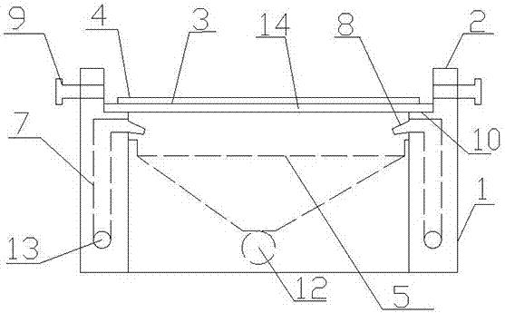
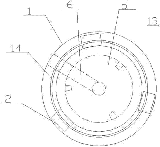
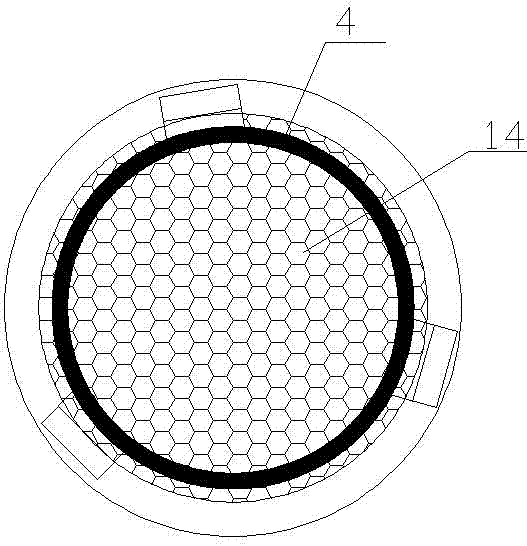
[0017] Such as Figure 1~Figure 4 As shown, a cleanable fixture for brake disc processing includes: a base 1, a set of jaws 2 are installed on the upper part of the base 1, a chuck 3 is installed on the jaws 2, symmetrical jaws 2 are installed on the edge of the base 1 , a double-layer chuck 3 is fixed between the claws 2, the upper layer of the chuck 3 is a hollow ring 4, the lower layer of the chuck 3 is a circular plate 14 with mesh holes, and the upper par...


PUM


Abstract

The invention provides a cleanable clamp for brake disc processing. The cleanable clamp for the brake disc processing is characterized in that a group of clamping jaws is mounted at the upper part of a base, wherein a chuck is mounted on the clamping jaws; symmetric clamping jaws are mounted at the side edge of the base, and a double-layer chuck is fixed between the clamping jaws; the upper layer of the chuck is provided with a hollow circular ring, and the lower layer of the chuck is provided with a circular plate which is provided with mesh pores; a funnel shaped groove is formed in the upper part of the base, and a waste channel is arranged from the bottom part of the groove to the outer wall of the base; a group of water feeding channels is arranged in the sidewall of the base; symmetric water outlets of the water feeding pipelines are arranged above the groove. The cleanable clamp for the brake disc processing has the beneficial effects that the structure is simple; the cost is low; chippings on a worktable can be effectively reduced during the processing through the groove in the base and an universal cooling pipe; the universal cooling pipe is capable of upwards spraying water to certainly cool a brake disc and the chuck; a processing station of the brake disc can be calibrated through the double-layer chuck, and the chippings on the brake disc can fall into the base, and moreover, the structure strength of the chuck can be improved.

Description

technical field [0001] The invention relates to the field of mechanical processing, in particular to a cleanable clamp for brake disc processing. Background technique [0002] In the process of machining, the machining equipment will change the size or performance of the workpiece. Machining is roughly divided into cutting and pressure processing. During the cutting process, a large amount of material is cut off from the workpiece. These materials When the particles are scattered on the processing equipment, it is easy to cause damage to the equipment and affect the machining accuracy of the workpiece. Therefore, there is an urgent need for a device that can collect particles in time, but in machining equipment, the equipment is at high speed. movement, so that the collection device must be operated together with the machining equipment to effectively reduce the phenomenon of particles splashing during processing [0003] When the brake disc is processed, the brake disc wil...

Claims


Application Information

Patent Timeline
Patent Type & Authority Applications(China)
IPC IPC(8): B23Q3/06B23Q11/10B23Q11/00
CPCB23Q3/062B23Q11/0042B23Q11/10
Inventor 彭朝阳
Owner 禹州市伟朔机械制造厂
Why Eureka
Try Eureka