
Metallic Lid For A Can

a lid and metal technology, applied in the field of metal lids, can solve the problem that the construction lacks the usual peripheral strength guarantee, and achieve the effect of increasing the thickness of the metal sh

Inactive Publication Date: 2008-07-24
BRASILATA S A EMBALAGENS METALICAS
View PDF11 Cites 0 Cited by
  • Summary
  • Abstract
  • Description
  • Claims
  • Application Information

AI Technical Summary

Benefits of technology

[0009]As a function of the deficiencies cited above and related to the metallic lids provided with a side wall to be frictionally seated and axially retained inside a seat defined in an opening of the can, it is an object of the present invention to provide a metallic lid of the type considered herein, which presents a higher structural strength, allowing it to be adequately and correctly closed, without requiring special cares when axial compressive forces are applied upon fitting the lid in the respective seat.
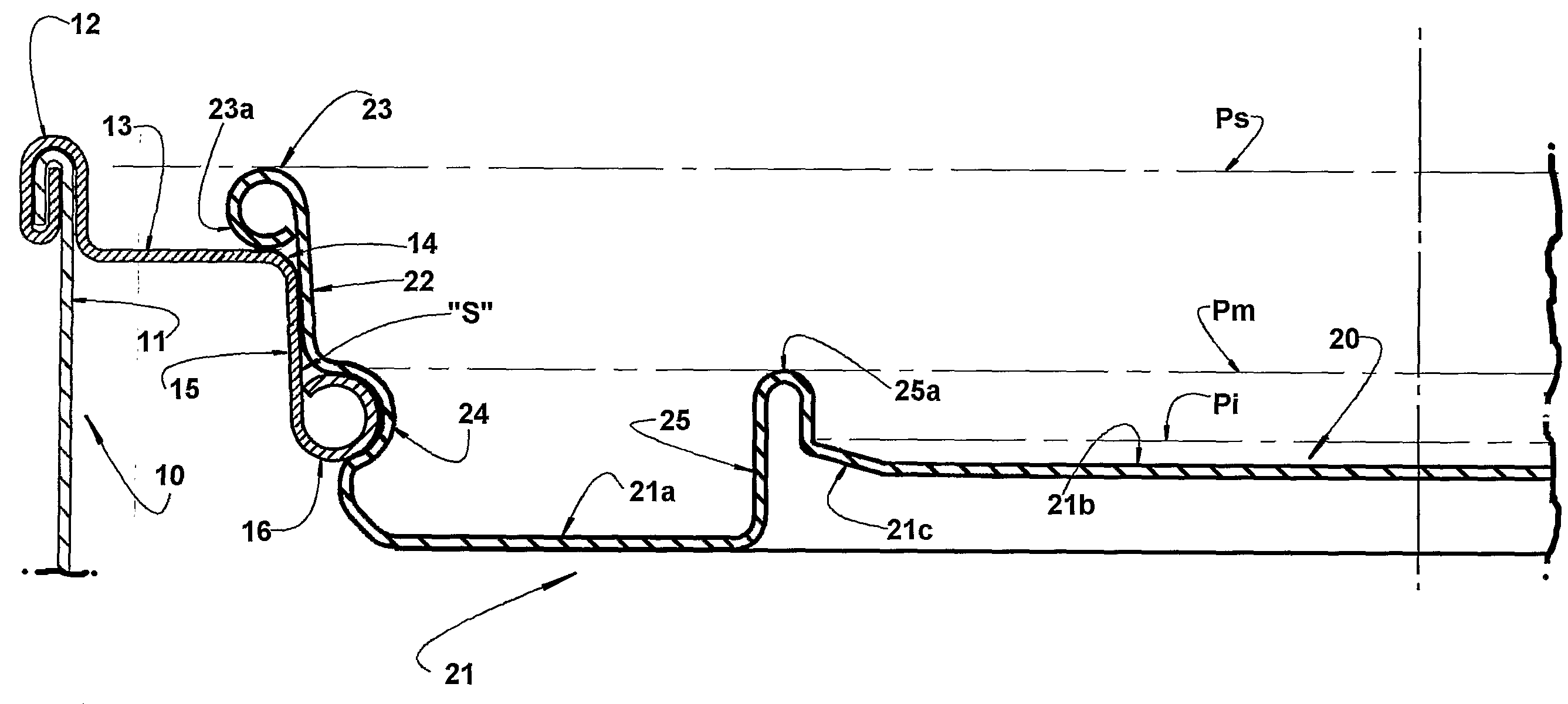
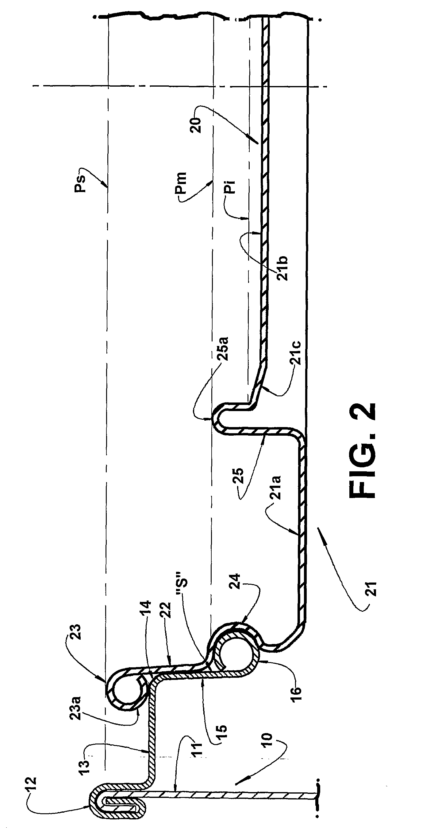
[0012]The provision of the annular rib portion imparts to the lid a structural strength that is substantially higher than that achieved with the prior art constructions mentioned above, with no need of increasing the thickness of the metal sheet that forms the lid.
[0013]Moreover, the construction of the lid object of the present invention can be achieved so as to maintain the median portion of the bottom wall in a higher plane in relation to the plane containing the peripheral annular portion of said bottom wall, allowing the median portion, jointly with the annular rib portion, to operate as a seating element for placing one lid over the other, when lids are stacked in a lid feeding device of a can closing machine.

Problems solved by technology

The structural deficiency mentioned above is due to the fact that said lid construction lacks the usual peripheral strength guaranteed in the metallic lids provided with a peripheral annular recess, generally with an inverted substantially trapezoidal cross section, to be frictionally seated in the interior of a recess with a complementary cross section an which defines a seat incorporated to the annular upper wall of a can body, such as in the construction known for decades and which is disclosed and illustrated in patent U.S. Pat. No. 795,126, filed in 1904.

Method used


Image

  • Metallic Lid For A Can
  • Metallic Lid For A Can
  • Metallic Lid For A Can

Examples


Embodiment Construction

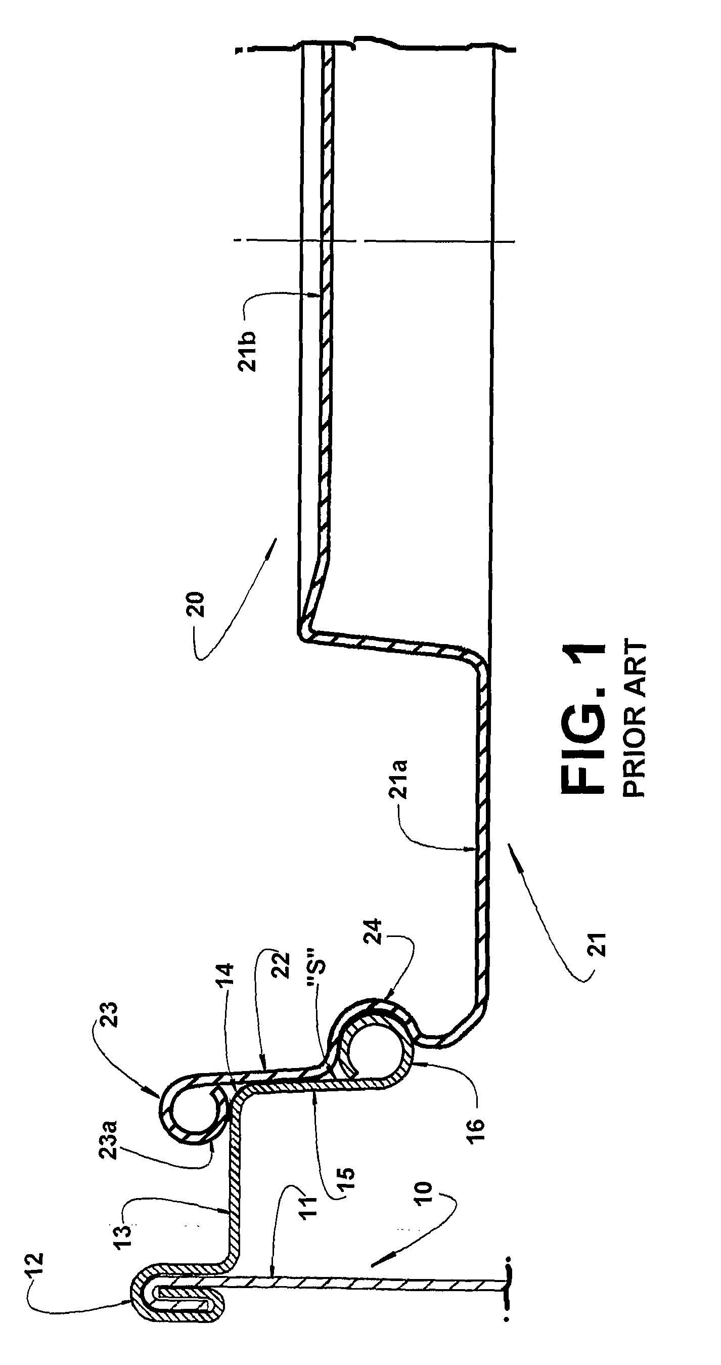
[0018]As illustrated in the appended drawings, the lid of the present invention is applied to a can 10, which is graphically illustrated only by the upper portion of its side wall 11, to whose upper edge 12 is affixed, usually by a double seam 12, an external peripheral edge of an annular upper wall 13 in whose median region is provided an opening 14 to whose edge is incorporated a depending tubular projection 15 which defines a seat (S) for the lid of the can. In the prior art construction shown in FIG. 1 of the drawings and which is object of Brazilian patent BR-PI 9408643-5 of the applicant of the present invention, the depending tubular projection 15 is provided with a lower end portion that is bent inwardly the opening 14, then upwardly and against the depending tubular projection 15, so as to form a continuous tubular rib 16 which can have, for example, a circular shape, as described in said prior art patent.

[0019]However, it should be understood that the construction of the d...


PUM


Abstract

A metallic lid for a can of the type which presents an opening defining a seating, said lid comprising, in a single piece, a bottom wall which incorporates, superiorly and peripherally, a side wall provided with a free upper edge and designed to be frictionally seated and axially retained in the interior of the seat. According to the invention, the bottom wall comprises a peripheral annular portion adjacent to the side wall, a median portion and an annular rib portion having the cross section in the approximate form of an inverted ‘U’, with the free edges of is lateral legs being respectively incorporated to the adjacent edges of the peripheral annular portion and median portion of the bottom wall.

Description

FIELD OF THE INVENTION[0001]The present invention refers to a metallic lid of the type having a peripheral side wall provided with a free upper edge and which is designed to be frictionally seated and axially retained in the interior of a seat defined in an upper opening of the can.BACKGROUND OF THE INVENTION[0002]Metallic lids of the type mentioned above are well known. They are formed in a single piece of metal sheet and comprise a generally disk shaped bottom wall, whose peripheral edge incorporates a side wall projecting upwardly, so as to be removably press fitted and axially retained inside a seat defined in an upper opening of a can. Said seat can be defined by a depending tubular projection which is superiorly incorporated to a median opening of the upper wall of a can with a circular or polygonal section.[0003]Metallic lids of the type mentioned above are disclosed and illustrated in patents U.S. Pat No. 2,074,231, U.S. Pat. No. 3,347,408, BR-MU8002622-2, BR-MU8002618-4, BR...

Claims


Application Information

Patent Timeline
Patent Type & Authority Applications(United States)
IPC IPC(8): B65D43/03B65D1/12B65D41/16
CPCB65D43/021B65D2543/00027B65D2543/00092B65D2543/00277B65D2543/00416B65D2543/00796B65D2543/00546B65D2543/00638B65D2543/00685B65D2543/00731B65D2543/00509B65D43/02
Inventor ALVARES, ANTONIO CARLOS TEIXEIRASENE, ANTONIO ROBERTO
Owner BRASILATA S A EMBALAGENS METALICAS
Learn More