Adjustable press machine

A press and adjustable technology, applied in the field of presses, can solve the problems of poor versatility, inability to adjust metal parts, small application range, etc., and achieve the effects of easy operation, improved application range, and improved work efficiency

Inactive Publication Date: 2017-07-25
芜湖瑞德机械科技有限公司
View PDF7 Cites 5 Cited by
  • Summary
  • Abstract
  • Description
  • Claims
  • Application Information

AI Technical Summary

Problems solved by technology

[0003] The purpose of the present invention is to provide a metal part with reasonable structure design, high work efficiency, and metal parts that can be punched according to the needs, aiming at the problems that the existing presses cannot be adjusted according to the metal parts that need to be punched, the application range is small, and the versatility is poor. Adjustable, wide-ranging and versatile adjustable presses

Method used


Image

  • Adjustable press machine
  • Adjustable press machine
  • Adjustable press machine

Examples


Embodiment 1

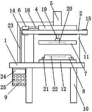
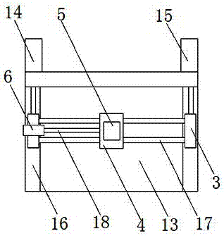
[0018] as attached Figure 1-3 As shown, an adjustable press includes an operating table 1, an adjustment frame 2, a slider 3, a fixed block 4, a cylinder one 5, a cylinder two 6, a stamping plate 7, a lower backing plate 8 and a control box 9. It is characterized in that: the operating table 1 is arranged on the bracket 10, and a fixing plate 11 and a positioning plate 12 are arranged on the operating table 1, and the adjusting frame 2 is arranged on the fixing plate 11, and is arranged on the adjusting frame 2 In the adjustment chamber 13, the third cylinder 14, the cylinder four 15, and on the two sides of the adjustment frame 2 opposite to the adjustment chamber 13 are arranged on the slideway 16, the cylinder three 14, the cylinder four 15 are respectively provided with adjustment rods 18, Connect the adjusting rods 18 on the third cylinder 14 and the cylinder four 15 to the slider 3 respectively, the slider 3 is arranged on the slideway 16, and a connecting rod is arrang...

Embodiment 2

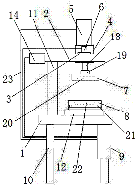
[0020] as attached Figure 4 As shown, an adjustable press includes an operating table 1, an adjustment frame 2, a slider 3, a fixed block 4, a cylinder 1 5, a cylinder 2 6, a stamping plate 7, a lower backing plate 8, a control box 9 and a walking The wheel 27 is characterized in that: the operating table 1 is arranged on the bracket 10, and a fixing plate 11 and a positioning plate 12 are arranged on the operating table 1, and the adjusting frame 2 is arranged on the fixing plate 11. The frame 2 is arranged on the adjusting chamber 13, the third cylinder 14, and the fourth cylinder 15, and is arranged on the slideway 16 on the opposite sides of the adjusting frame 2 of the adjusting chamber 13. The three cylinders 14 and the fourth cylinder 15 are respectively provided with Adjust the rod 18, and connect the adjustment rods 18 on the cylinder three 14 and the cylinder four 15 to the slider 3 respectively. The slider 3 is arranged on the slideway 16 and between the slider 3 a...


PUM


Abstract

Disclosed is an adjustable press machine. The adjustable press machine comprises an operating platform, an adjusting frame, sliding blocks, a fixing block, a first air cylinder, a second air cylinder, a stamping plate, a lower cushion plate and a control cabinet. The adjustable press machine is characterized in that the operating platform is arranged on a support, the adjusting frame is arranged on a fixing plate, and an adjusting cavity, a third air cylinder and a fourth air cylinder are arranged on the adjusting frame. According to the adjustable press machine, sliding channels are formed in the two sides of the adjusting frame, the sliding blocks are arranged on the sliding channels, a connecting rod is arranged between the sliding blocks, and the fixing block is arranged on the connecting rod; the second air cylinder on one sliding block is connected with the fixing block through the connecting rod, and therefore the fixing block can be adjusted to slide back and forth on the connecting rod through the second air cylinder; the sliding blocks are connected with connecting rods of the third air cylinder and the fourth air cylinder, and can move on the sliding channels through the third air cylinder and the fourth air cylinder, the position of the fixing block in the adjusting frame can be adjusted, then the position of the stamping plate can be adjusted, and therefore the adjustable press machine is suitable for different processed workpieces, and the application range of the press machine is broadened.

Description

technical field [0001] The invention relates to the technical field of presses, in particular to an adjustable press. Background technique [0002] Press is a kind of production equipment commonly used in metal stamping and forming, which has the advantages of wide range of uses and high work efficiency. However, in the process of metal parts processing, various metal parts will be processed. Generally, there is a situation where the presses that do not have the function of replacing or adjusting the mold cannot be processed. For example, the patent with the application number of 201610627584.4 discloses a stamping press, which solves the problem that the mechanical transmission cannot meet the production requirements, but it has the problems that the press cannot be adjusted according to the metal parts that need to be stamped, the scope of application is small, and the versatility is poor of insufficiency. SUMMARY OF THE INVENTION [0003] The purpose of the present in...

Claims


Application Information

Patent Timeline
Patent Type & Authority Applications(China)
IPC IPC(8): B30B15/00B21D22/00
CPCB30B15/0035B21D22/00
Inventor 卢国孝江荧
Owner 芜湖瑞德机械科技有限公司
Why Eureka
Try Eureka