Temperature and humidity detection device, dehumidifier and dehumidification method

A detection device, temperature and humidity technology, applied in the direction of heating methods, mechanical equipment, lighting and heating equipment, etc., can solve the problems affecting the detection accuracy of sensors, and achieve the effects of improving user experience, sufficient heat and humidity exchange, and accurate temperature and humidity values

Pending Publication Date: 2017-07-25
GREE ELECTRIC APPLIANCES INC
View PDF8 Cites 5 Cited by
  • Summary
  • Abstract
  • Description
  • Claims
  • Application Information

AI Technical Summary

Problems solved by technology

The temperature and humidity sensor is only in contact with the air through the vent hole of the top cover, and the surrounding air and the sensor are relatively static, so what the s

Method used


Image

  • Temperature and humidity detection device, dehumidifier and dehumidification method
  • Temperature and humidity detection device, dehumidifier and dehumidification method
  • Temperature and humidity detection device, dehumidifier and dehumidification method

Examples


Embodiment Construction

[0036] The first core of the present invention is to provide a temperature and humidity detection device to improve detection accuracy; the second core of the present invention is to provide a dehumidifier and a dehumidification method.

[0037] The temperature and humidity detection device of the existing dehumidifier is basically installed between the air inlet and the evaporator. When the dehumidifier is running normally, the temperature and humidity detected by the temperature and humidity detection device are relatively accurate, which can control the work of the dehumidifier well. Meet the needs of users. But when the room humidity drops to the set humidity, the dehumidifier stops working. When the dehumidifier just stops working, the temperature of the evaporator is low, and there is moisture on the surface. After the dehumidifier stops working, the temperature of the evaporator rises, and the water on the surface evaporates. As a result, the humidity of the air near th...


PUM


Abstract

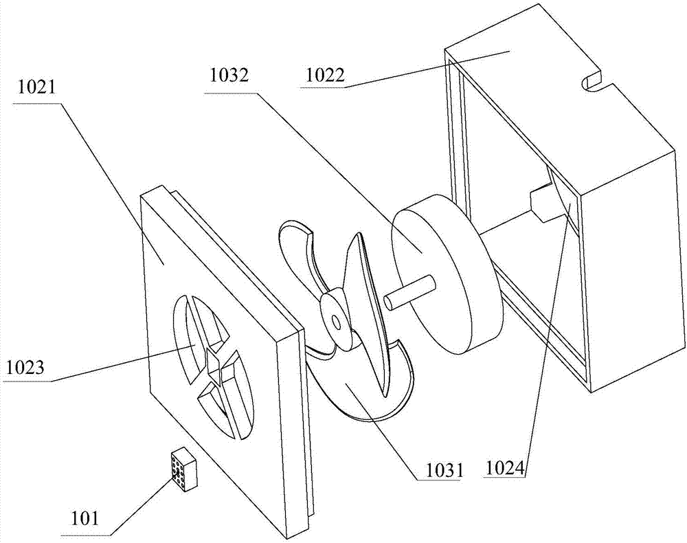
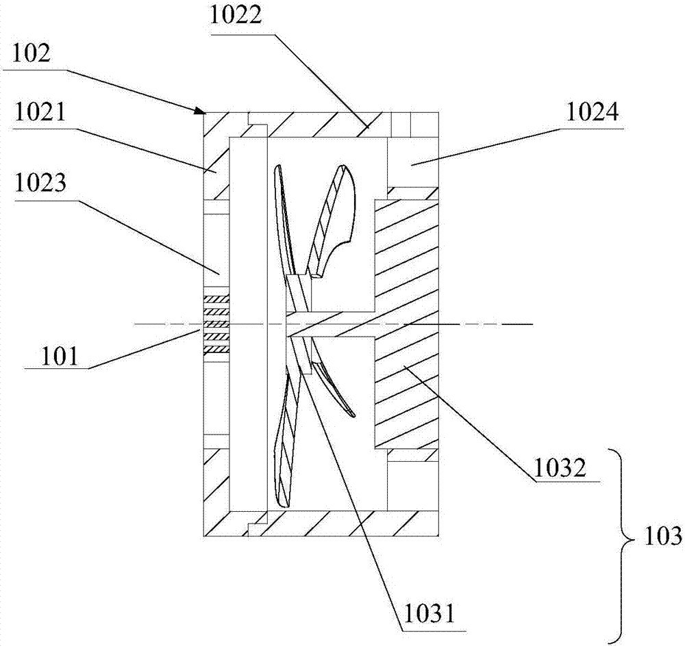
The embodiment of the invention discloses a temperature and humidity detection device, a dehumidifier and a dehumidification method. According to the temperature and humidity detection device, a temperature and humidity detection module is arranged at an air inlet hole of a shell, a first fan is arranged in the shell, the first fan drives air inside the shell to flow during operating, and thus, the air can enter from the air inlet hole and is exhausted from an air outlet hole; and accordingly, the effect that air surrounding the surface of the temperature and humidity detection module is not retained can be kept, sufficient heat and humidity exchange between the air and the temperature and humidity detection module can be achieved, the detected temperature and humidity values are more accurate, and the user experience is greatly improved.

Description

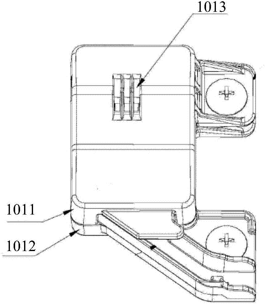
technical field [0001] The invention relates to the technical field of temperature and humidity detection, and more specifically, to a temperature and humidity detection device, a dehumidifier and a dehumidification method. Background technique [0002] see figure 1 , figure 1 A schematic structural diagram of a sensor electrical box provided in the prior art. [0003] The sensor electrical box is suitable for humidity sensors, temperature sensors, etc. It includes a base 1011 and a top cover 1012 tightly fastened with the base 1011. The base 1011 and the top cover 1012 form an installation chamber for accommodating the sensor. The top cover 1012 is provided with a vent hole 1013, and the external air can only pass through the top cover 1012 The vent hole 1013 provided on it enters the installation chamber. The temperature and humidity sensor is only in contact with the air through the vent hole of the top cover, and the surrounding air and the sensor are relatively stat...

Claims


Application Information

Patent Timeline
IPC IPC(8): F24F3/147F24F11/00
CPCF24F3/147F24F11/30F24F11/62F24F11/64
Inventor 潘荣飞杨述华梁耀祥陈勇廖磊
Owner GREE ELECTRIC APPLIANCES INC
Why Eureka
Try Eureka