Plate rolling heat exchange body, heat exchanger facilitating medium flowing and heat exchange method

A technology of medium flow and heat exchange body, applied in indirect heat exchangers, heat exchanger types, heat exchanger shells, etc., can solve the problems of unclear arrangement of spoilers, unsolved disassembly and cleaning of heat exchangers, etc. Achieve improved flow, simple processing and flexible settings

Active Publication Date: 2017-07-25
ANHUI UNIVERSITY OF TECHNOLOGY +1
View PDF11 Cites 2 Cited by
  • Summary
  • Abstract
  • Description
  • Claims
  • Application Information

AI Technical Summary

Problems solved by technology

But first of all, the spoiler setting scheme disclosed in this application is very unclear, and secondly, it does not solve the problem of disassembly and cleaning of the heat exchanger, which still needs further improvement

Method used


Image

  • Plate rolling heat exchange body, heat exchanger facilitating medium flowing and heat exchange method
  • Plate rolling heat exchange body, heat exchanger facilitating medium flowing and heat exchange method
  • Plate rolling heat exchange body, heat exchanger facilitating medium flowing and heat exchange method

Examples


Embodiment 1

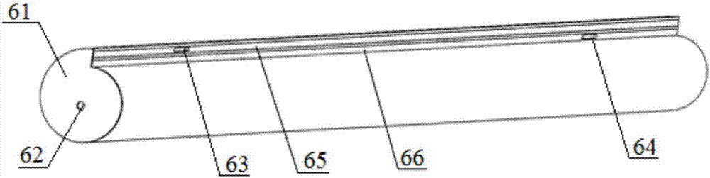
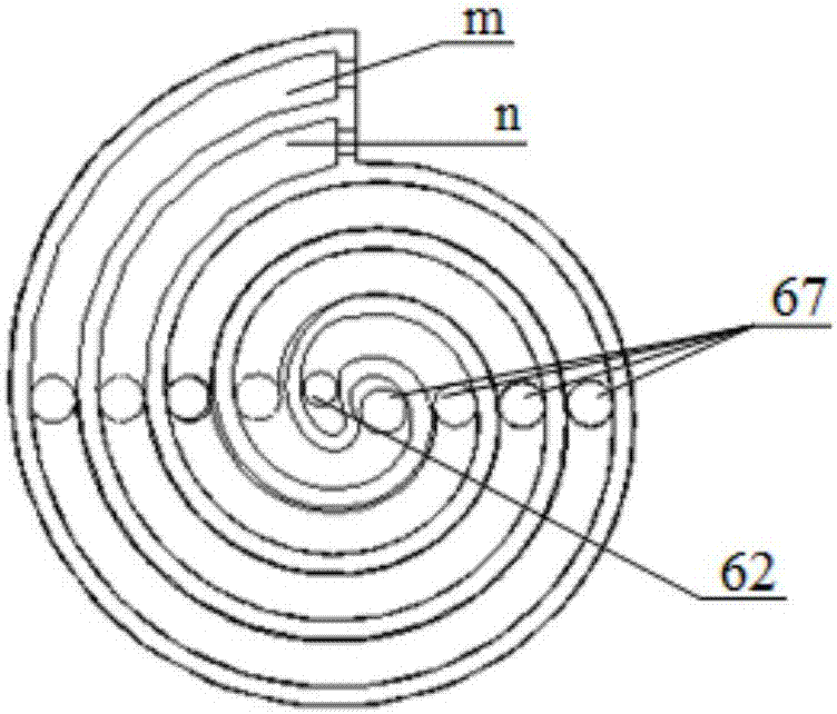
[0041] combine figure 2 and image 3 , a coiled plate heat exchange body in this embodiment includes a tube seal 61, a first horizontal plate 65, a second horizontal plate 66 and a flat plate 68, and the coiled plate heat exchange body 6 is folded in half by a flat plate 68 Afterwards, it is rolled along the same direction, and the inside of the rolled tubular body forms ring tracks m and n. Pipe seals 61 are arranged on both sides of the tubular body, and a through hole 62 is opened on the pipe seal 61. One side of the through hole 62 communicates with the circular track m, and the other side of the through hole 62 communicates with the circular track n. The upper and lower outlets of the tubular main body along the axial direction The places are respectively closed by a first horizontal plate 65 and a second horizontal plate 66, the first horizontal plate 65 is provided with a first horizontal plate through hole 63, and the second horizontal plate 66 is provided with a sec...

Embodiment 2

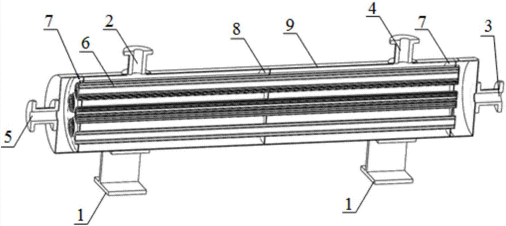
[0044] combine figure 1 , a heat exchanger for medium flow in this embodiment, including a support 1, a flow medium a inlet 2, a flow medium a outlet 3, a flow medium b inlet 4, and a flow medium b outlet 5, as described in embodiment 1 The coiled plate heat exchanger 6, the tube sheet 7, the intermediate partition plate 8 and the heat exchanger shell 9. The heat exchanger of this embodiment is a horizontal heat exchanger, the bottom of the heat exchanger shell 9 is supported by the support 1, and the intermediate partition 8 is arranged inside the heat exchanger shell 9, see Figure 10 , the intermediate partition 8 is provided with a plurality of mounting holes 81 that conform to the shape of the coiled plate heat exchange body 6, and the coiled plate heat exchange body 6 is inserted into the mounting holes 81, and through the tube plates 7 arranged symmetrically on both sides of the heat exchanger, Fixed, the shape and structure of the tube plate 7 is the same as that of t...

Embodiment 3

[0050] combine Figure 6 and Figure 7 , a coiled plate heat exchanger, a heat exchanger conducive to medium flow, and a heat exchange method in this embodiment are basically the same as in Embodiment 2, except that: in this embodiment, there are many obliquely spaced arrangements on the flat plate 68. Thin strip-shaped spacers 67 are arranged, and the spacers 67 in this embodiment are semicircular spacers 672, and the cross-section of the semicircular spacers 672 is semicircular. The coiled plate heat exchangers 6 are arranged in the form of a corner triangle on the middle partition plate 8 .


PUM


Abstract

The invention discloses a plate rolling heat exchange body, a heat exchanger facilitating medium flowing of and a heat exchange method and belongs to the technical field of heat exchangers. The heat exchanger comprises flowing medium inlets, flowing medium outlets, the plate rolling heat exchange body, an intermediate partitioning plate and a heat exchanger shell body. The intermediate partitioning plate is arranged inside the heat exchanger shell body. A plurality of installing holes are formed in the intermediate partitioning plate. The plate rolling heat exchange body is inserted into the mounting holes. The flowing medium inlets communicate with a first transverse plate through hole and a second transverse plate through hole. The flowing medium outlets communicate with through holes in the two sides of the plate rolling heat exchange body. The plate rolling heat exchange body is formed by the step that a flat plate is folded in the position one half of the flat plate and then rolled in the same direction, an annular track m and an annular track n are formed inside the plate rolling heat exchange body, and slender spacing bodies are arranged obliquely on the flat plate. The heat exchange bodies composing one of heat exchanger structures all adopt plate rolling heat exchange body structures, so that arbitrary combination and installing can be conducted according to installing spaces and occasions, processing is simple, and installing and maintenance are convenient.

Description

technical field [0001] The invention relates to the technical field of heat exchangers, and more specifically, to a coiled plate heat exchange body, a heat exchanger conducive to medium flow, and a heat exchange method. Background technique [0002] Due to environmental pollution problems, traditional electric heating, boilers and other low-efficiency and heavily polluting hot water devices will be gradually discontinued and replaced by high-efficiency heat pump hot water devices. At present, heat exchangers used in heat pump water heating devices are mainly divided into two types: casing type and plate type. For example, the heat exchange body of the current coaxial body combined heat exchanger is mainly composed of steel pipes. Practice has proved that although a heat exchanger composed of multiple steel pipe heat exchangers has high heat exchanger efficiency and pressure bearing capacity, its application is limited by the size of the steel pipes. In order to adapt to di...

Claims


Application Information

Patent Timeline
Patent Type & Authority Applications(China)
IPC IPC(8): F28D9/04F28F9/26
CPCF28D9/0037F28D9/04F28F9/26
Inventor 谢能刚孙东德胡晓磊王璐李振东王闪
Owner ANHUI UNIVERSITY OF TECHNOLOGY
Why Eureka
Try Eureka