
Caterpillar track type self-propelled fodder ramie combined harvester

A combine harvester, self-propelled technology, applied in the direction of harvesters, applications, cutters, etc., can solve the problems of entanglement of moving parts, high internal fiber strength, hard stems, etc., to achieve a high degree of mechanization and high operating efficiency , High stability effect

Inactive Publication Date: 2017-07-28
INST OF BAST FIBER CROPS CHINESE ACADEMY OF AGRI SCI +2
View PDF8 Cites 2 Cited by
  • Summary
  • Abstract
  • Description
  • Claims
  • Application Information

AI Technical Summary

Problems solved by technology

[0003] Because the stems of wheat and rice are slender, soft and relatively low, the traditional single-auger cutting bucket can meet the requirements of use
And the plant length of forage ramie, the stem is hard, and the intensity of internal fiber is big, and fiber is thick, quite tough, because above-mentioned reason, present combined harvesting machine has following problem when harvesting ramie: (1) the ramie after cutting down The plant is long, and it is easy to hang out after being dialed into the cutting bucket by the reel; (2) The ramie stalks for feeding are hard, unlike the slender and soft grain stalks, which are difficult to move with the auger, so it is easy to appear. Does not move with the auger to the conveying slot, resulting in difficulty in feeding
[0004] In addition, the existing combine harvester can only achieve chopping, and a blower must be configured to blow out the crops. In terms of function, it is the working mode of chopping first and then blowing out
When cutting high-fiber crops such as hemp, because the blowing and chopping are not carried out at the same time, if the fiber cannot be blown out in time during the chopping, it is very easy to entangle the moving parts and cause the machine to stop

Method used


Image

  • Caterpillar track type self-propelled fodder ramie combined harvester
  • Caterpillar track type self-propelled fodder ramie combined harvester
  • Caterpillar track type self-propelled fodder ramie combined harvester

Examples


Embodiment Construction

[0027] In order to make the object, technical solution and advantages of the present invention clearer, the present invention will be further described in detail below in conjunction with the accompanying drawings and embodiments. It should be understood that the specific embodiments described here are only used to explain the present invention, not to limit the present invention.

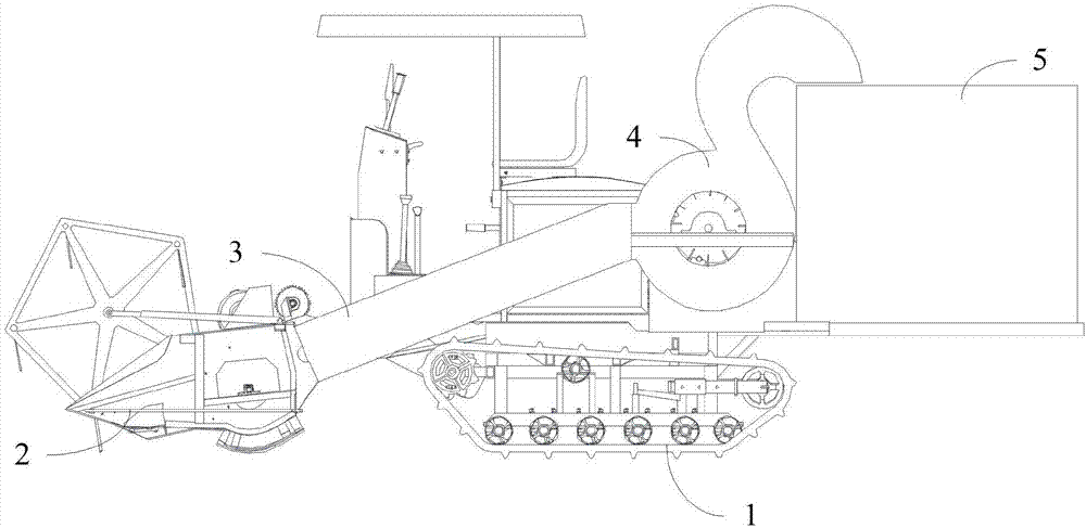
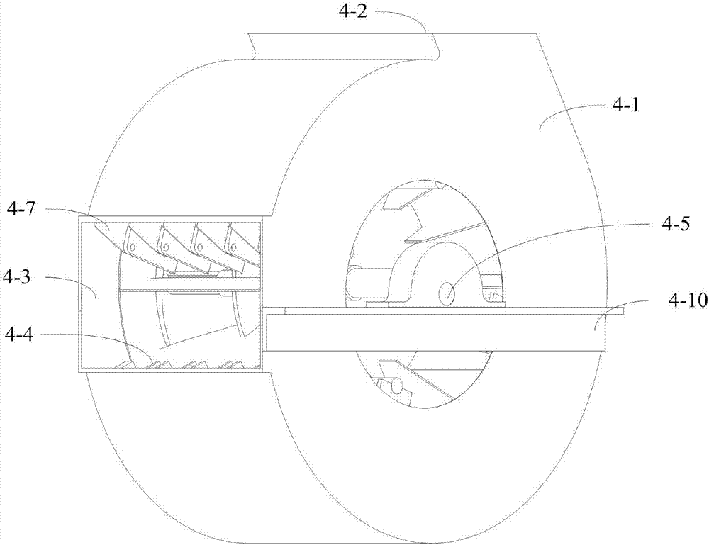
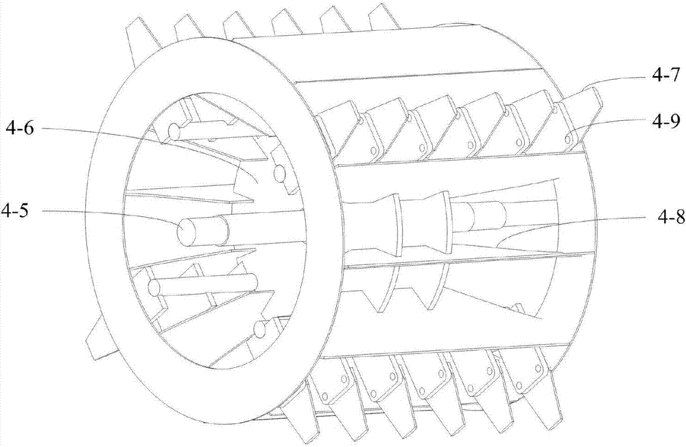
[0028] Such as Figure 1~6 As shown, among them, figure 1 It is a structural schematic diagram of the crawler self-propelled feeding ramie combine harvester of the present invention; figure 2 It is the structural representation of the rotary knife blower in the combine harvester of the present invention; image 3 It is a structural schematic diagram of the rotary knife blower device in the rotary knife blower of the present invention; Figure 4 It is a schematic structural view of the cutting bucket in the combine harvester of the present invention in the state where the reel is not installed; ...


PUM


Abstract

The invention discloses a caterpillar track type self-propelled fodder ramie combined harvester. A cutting hopper, a feeding cylinder and a rotating knife type air blower of the harvester are connected in sequence. A feeding caterpillar track is arranged inside the feeding cylinder. A discharging outlet of the rotating knife type air blower is located over an opening of an aggregate box; the rotating knife type air blower comprises an air blowing cylinder and a rotating knife air blowing device; a discharging outlet is formed in the top end of an arc face of the air blowing cylinder, a feeding inlet is formed in the front end of the arc face of the air blowing cylinder, a row of fixed cutters are installed inside the air blowing cylinder, and the fixed cutters are located on the edge of the lower side of the feeding inlet; the rotating knife type air blowing device comprises a rotating shaft, a rotating disc, movable cutters and air blowing blades; the movable cutters and the air blowing blades are installed on the arc side of the rotating disc, and a row of movable cutters are arranged between every two adjacent air blowing blades; the rotating shaft is installed in the axis of the rotating disc, and the two ends of the rotating shaft are installed on the side wall of the axis of the air blowing cylinder in a bearing mode. Cutting, shredding and storage are integrated, and the harvester is suitable for harvesting of fiber crops with the large strophism, high fiber and high tenacity.

Description

technical field [0001] The invention belongs to the field of agricultural machinery, in particular to a crawler self-propelled feeding ramie combine harvester. Background technique [0002] Combine harvesting machinery is widely used in wheat, rice and other crop fields, and the technology is mature. Most of the harvesting components of the harvesters are in the form of cutting buckets. The general structure of the cutting bucket includes the functions formed by the cutter-reel-auger The chain can realize the predetermined function. The working process of the cutting bucket is as follows: first, the crop is cut off near the root by the cutting knife, and then the cut stems are pushed inward by the reel into the cutting bucket shell, and then arranged horizontally. The auger sends it into the conveying function component through the stirring of the helical blade to complete the function of the cutting bucket. [0003] Because the stalks of wheat and rice are slender, soft an...

Claims


Application Information

Patent Timeline
IPC IPC(8): A01D41/02A01D43/08
CPCA01D41/02A01D43/08
Inventor 唐守伟刘凯戴求仲魏仲珊籍飞超刘头明朱四元王延周吴端钦郑霞
Owner INST OF BAST FIBER CROPS CHINESE ACADEMY OF AGRI SCI
Learn More