Bumper framework used for reducing collision force

A technology of bumper skeleton and impact force, which is applied in the direction of bumper, vehicle safety arrangement, transportation and packaging, etc., to achieve the effect of ensuring operation, ensuring safety and working stability

Inactive Publication Date: 2017-07-28
CHENGDU KELIFU SCI & TECH
View PDF4 Cites 1 Cited by
  • Summary
  • Abstract
  • Description
  • Claims
  • Application Information

AI Technical Summary

Problems solved by technology

[0004] The technical problem to be solved by the present invention is to effectively protect the occupants of the vehicle through the bumper frame when the frontal impact force is too large, and the purpose is to provide a bumper frame for reducing the impact force and solve the above-mentioned problems

Method used


Image

  • Bumper framework used for reducing collision force
  • Bumper framework used for reducing collision force

Examples


Embodiment 1

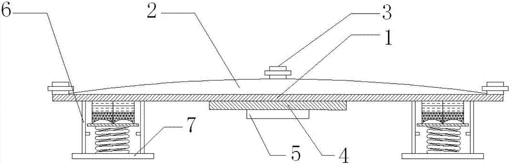
[0020] like figure 1 As shown, the bumper frame used to reduce the impact force of the present invention includes a protective cover 2 arranged on the push-out platform 1, the upper end surface of the middle part of the protective cover 2 and the left and right sides of the upper end surface of the push-out platform 1 are provided with bolts 3, and the push-out platform 3. A structural reinforcing plate 4 is installed under the middle part, and a control device 5 is installed under the structural reinforcing plate 4. The push-out device 6 is installed on the left and right sides of the lower end surface of the push-out platform 3. When the vehicle is hit, the sensor installed on the frame transmits the signal. To the control device 5, the control device 5 sends a signal to the ejection device 6, and the ejection device 6 pushes the ejection platform 1 forward to offset the impact force when the vehicle hits.

Embodiment 2

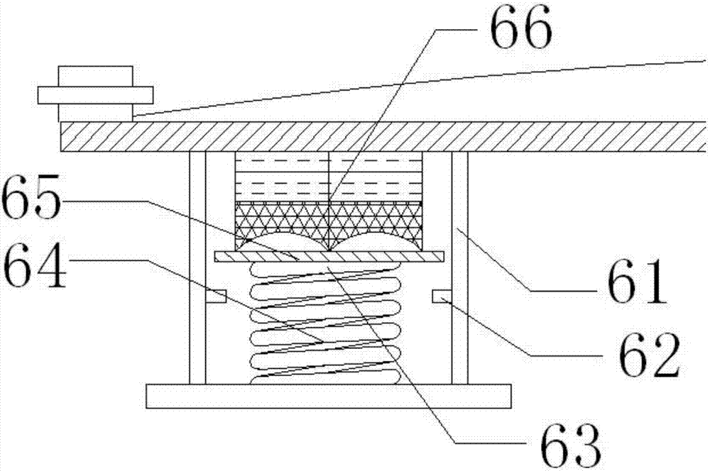
[0022] like figure 1 , 2 As shown, the push-out device 6 includes a push-out bin 61, a gear block 62 arranged on the wall of the push-out bin 61, and a pusher 63 installed in the middle of the push-out device 6, and the pusher 63 is sequentially provided with springs from bottom to top. 64. Orientation plate 65, directional blasting device 66. After the push-out device 6 receives the signal from the control device 5, the directional blasting device 66 starts to push the push-out platform 1. The wall of the ejection warehouse is made of stainless steel 316L, which has good explosion-proof performance. Directional blasting in the ejection chamber can also ensure that the warehouse wall is intact and not easy to crack. Springs and gear blocks are provided to ensure safety when the control device fails. When the bar frame has been deformed, when the directional plate touches the gear block by pressing down the spring, the directional blasting device starts to reversely impact the...


PUM


Abstract

The invention discloses a bumper framework used for reducing collision force. The bumper framework comprises a protecting cover arranged on a push-out platform; bolts are arranged on the upper end face of the middle of the protecting cover and the left and right sides of the upper end face of the push-out platform; a structure reinforcing plate is mounted on the lower portion of the middle of the push-out platform; a control device is arranged below the structure reinforcing plate; and push-out devices are arranged on the left and right sides of the lower end face of the push-out platform. When a vehicle is collided, a sensor mounted on a vehicle frame sends signals to the control device, the control device send the signals to the push-out devices, and the push-out devices push the push-out platform forward to counteract the collision force when the vehicle is collided. Each push-out device comprises a push-out bin, a gear block arranged on the wall of the push-out bin and a pusher mounted in the middle of the push-out device. A spring, a directional plate and a directional blasting device are arranged on each pusher in sequence from bottom to top. When the push-out devices receive the signals of the control device, the directional blasting devices are started to push the push-out platform.

Description

technical field [0001] The invention relates to a vehicle protection device, in particular to a bumper frame for reducing impact force. Background technique [0002] The shock absorber of the bumper is a part that is used by the mounting layer to reduce the conduction of the shock generated during the Jehol collision to the subject, and the shock absorber is made of a natural rubber type material, but when in When comparing the elastic characteristics, its elasticity is not enough compared with the elasticity obtained by applying the improvement, so the present invention does not adopt the generally used foam filling structure, but selects the mechanical structure to supplement the elastic force. At the moment of collision, the energy can be Absorb and reduce damage to vehicles and occupants. [0003] For the safety of passengers and the car body, most vehicles will be equipped with bumpers. With the advancement of technology, and people's requirements for vehicles have cha...

Claims


Application Information

Patent Timeline
IPC IPC(8): B60R19/02B60R19/24
CPCB60R19/023B60R19/24
Inventor 胡明容
Owner CHENGDU KELIFU SCI & TECH
Why Eureka
Try Eureka