a zoom lens

A zoom lens and lens technology, applied in the field of zoom lenses, can solve the problem of inability to take into account the total optical length and the total optical length, etc.

Active Publication Date: 2019-06-18
JIAXING ZHONGRUN OPTICAL TECH
View PDF7 Cites 2 Cited by
  • Summary
  • Abstract
  • Description
  • Claims
  • Application Information

AI Technical Summary

Problems solved by technology

[0008] The reason why similar lenses cannot take into account the longer focal length and shorter optical total length has an important relationship with its optical structure
This type of miniaturized zoom lens currently on the market adopts a two-group or three-group structure without exception. This structure will inevitably result in an excessively long optical length.

Method used


Image

  • a zoom lens
  • a zoom lens
  • a zoom lens

Examples


Embodiment 1

[0087] Refer below figure 1 , 2 , to illustrate the first embodiment of the present invention.

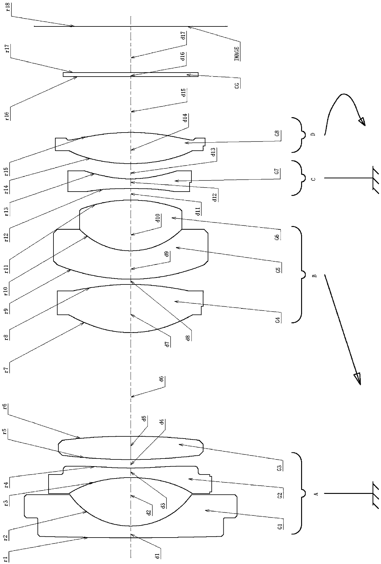
[0088] figure 1 It is a cross-sectional view along the optical axis showing the configuration of the zoom lens of Example 1. The zoom lens is arranged in sequence along the light incident direction, the first lens group A with negative refractive power, the second lens group B with positive refractive power, the third lens group C with negative refractive power, and the light The focal power is positive fourth lens group D.

[0089] In addition, a cover glass CG is disposed between the fourth lens group D and the imaging plane IMAGE. The protective glass CG can be arranged as needed, and can be omitted when not needed. In addition, on the imaging surface IMAGE, a light-receiving surface of a solid-state imaging element such as a CCD or a CMOS is disposed.

[0090] The first lens group A, whose refractive power is negative, includes the first lens G1, the second lens G2 and th...

Embodiment 2

[0179] Refer below figure 1 , 3 , to illustrate the second embodiment of the present invention.

[0180] figure 1 It is a sectional view along the optical axis showing the configuration of the zoom lens of Example 2. The zoom lens is arranged in sequence along the light incident direction, the first lens group A with negative refractive power, the second lens group B with positive refractive power, the third lens group C with negative refractive power, and the light The focal power is positive fourth lens group D.

[0181] In addition, a cover glass CG is disposed between the fourth lens group D and the imaging plane IMAGE. The protective glass CG can be arranged as needed, and can be omitted when not needed. In addition, on the imaging surface IMAGE, a light-receiving surface of a solid-state imaging element such as a CCD or a CMOS is disposed.

[0182]The first lens group A, whose refractive power is negative, includes the first lens G1, the second lens G2 and the thir...

Embodiment 3

[0271] Refer below figure 1 , 4 , to illustrate the third embodiment of the present invention.

[0272] figure 1It is a sectional view along the optical axis showing the configuration of the zoom lens of Example 3. The zoom lens is arranged in sequence along the light incident direction, the first lens group A with negative refractive power, the second lens group B with positive refractive power, the third lens group C with negative refractive power, and the light The focal power is positive fourth lens group D.

[0273] In addition, a cover glass CG is disposed between the fourth lens group D and the imaging plane IMAGE. The protective glass CG can be arranged as needed, and can be omitted when not needed. In addition, on the imaging surface IMAGE, a light-receiving surface of a solid-state imaging element such as a CCD or a CMOS is disposed.

[0274] The first lens group A, whose refractive power is negative, includes the first lens G1, the second lens G2 and the third...


PUM


Abstract

A zoom lens is disclosed. An optical system consists, sequentially along a light incident direction, of a first lens group A having a negative focal power, a second lens group B having a positive focal power, a diaphragm S, a third lens group C having a negative focal power and a fourth lens group D with a positive focal power. The first lens group A and the third lens group C are always in a fixed state. The second lens group B is moved from an image side to an object side along the optical axis so that the lens field angle is zoomed from a wide-angle end to a telephoto end. At the same time, the fourth lens group D is moved correspondingly in a non-linear manner along the optical axis for correction and focusing with the image variation accompanying the zooming. The stability of the system image during the variation in the focal length is ensured.

Description

technical field [0001] The invention relates to a zoom lens, in particular to a low-cost, small-volume, light-weight, high-performance, large-aperture zoom lens that can replace common fixed-focus lenses in many occasions and has an auto-focus function. Background technique [0002] The world's first real zoom lens appeared as early as the beginning of the 20th century, but due to the imperfection of precision machining technology, coating technology, and optical cold processing technology, the optical design and practical application of the zoom lens have been greatly affected. Big restrictions. So even now that the technical means have been perfected, zoom lenses have not been widely used, lagging far behind the application of fixed-focus lenses. [0003] However, the conventional fixed-focus lens has only one focal length, which is very inconvenient for observation when the field of view of the monitoring site needs to be changed. With the rapid development of science a...

Claims


Application Information

Patent Timeline
Patent Type & Authority Patents(China)
IPC IPC(8): G02B15/177
CPCG02B15/177
Inventor 葛航笠徐雄飞尚洁阳盛亚茗张平华
Owner JIAXING ZHONGRUN OPTICAL TECH
Why Eureka
Try Eureka